JVC AV-27F703 User Guide - Page 14
Cable and VCR Connections - Continued
 |
UPC - 046838206337
View all JVC AV-27F703 manuals
Add to My Manuals
Save this manual to your list of manuals |
Page 14 highlights
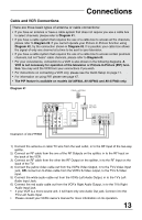
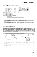
Connections Cable and VCR Connections - Continued Diagram #2 CABLE or ANTENNA OUT AUDIO VIDEO S VIDEO R L MONO OVER INPUT 1 INPUT 2 INPUT 4 AUDIO COMPONENT VIDEO R L MONO COMPONENT VIDEO R L Y AUDIO OUT PB AV COMPULINK PR 75Ω (VHF / UHF) OR OUT IN Cable Box VCR IN VLR OUT OR Illustration of AV-27F803 1) Connect the antenna or cable TV wire from the wall outlet, in to the RF Input of the cable box. 2) Connect an RF cable from the RF Output of the cable box, in to the RF Input on the back of the VCR. 3) Connect an RF cable from the RF Output of the VCR, in to the RF Input on the back of the TV. 4) Connect the yellow video cable out from the VCR's Video Output, in to the TV's Video Input jack, OR connect an S-Video cable from the VCR's S-Video output, to the TV's S-Video input. 5) Connect the white audio cable out from the VCR's Left Audio Output, in to the TV's Left Audio Input Jack. 6) Connect the red audio cable out from the VCR's Right Audio Output, in to the TV's Right Audio Input jack. • Please see page 47 for information on using the PIP feature with a Cable Box. • If your VCR is a mono sound unit, it will have only one Audio Out jack. Connect it to the TV's Left Audio Input. • Please consult your VCR's owner's manual for more information on its operation. 14
-
 1
1 -
2
-
3
-
4
-
5
-
6
-
7
-
8
-
 9
9 -
 10
10 -
 11
11 -
 12
12 -
 13
13 -
 14
14 -
 15
15 -
 16
16 -
 17
17 -
 18
18 -
 19
19 -
20
-
21
-
22
-
23
-
24
-
25
-
26
-
27
-
28
-
29
-
30
-
31
-
32
-
33
-
34
-
35
-
36
-
37
-
38
-
39
-
40
-
41
-
42
-
43
-
44
-
45
-
46
-
47
-
48
-
49
-
50
-
51
-
52
-
53
-
54
-
55
-
56
-
57
-
58
-
59
-
60
-
61
-
62
-
63
-
64
-
65
-
66
-
67
-
68
-
69
-
70
-
71
-
72
-
73
-
74
-
75
-
76
-
77
-
78
-
79
-
80
-
81
-
82
-
83
-
84
-
85
-
86
-
87
-
88
-
89
-
90
-
91
-
92
-
93
-
94
-
95
-
96
-
97
-
98
-
99
-
100
-
101
-
102
-
103
-
104
-
105
-
106
-
107
-
108
-
109
-
110
-
111
-
112
 |
 |
