JVC C11U Instruction Manual - Page 14
Connecting the Power Cord, Preparations Step 1 Connection and Installation
 |
UPC - 046838325670
View all JVC C11U manuals
Add to My Manuals
Save this manual to your list of manuals |
Page 14 highlights
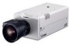
Preparations (Step 1 Connection and Installation) 1-2 Connecting the Power Cord Connect the camera to DC 12 V or AC 24 V. To Power DC12V AC24V CLASS 2 ONLY For USA ISOLATED POWER ONLY For EUROPE INPUT OUTPUT 1 2 G 2 1 OUT COM Power indicator lamp ALARM PUSH POWER MONITOR OUT 10BASE-T/100BASE-TX For USA DO NOT CONNECT TO THE TELEPHONE NETWORK The power indicator is lit when the power is turned on. Power Cord • Do not connect the power cord to DC 12 V and AC 24 V at the same time. • Use a lug plate to securely connect the power cord to the power terminals and avoid misconnection or loose connection. • For DC 12 V connection, ensure that the polarities, positive and negative, are correctly oriented. • For DC 12 V connection, the ripple voltage should not exceed 50 mV. Length: 30 m maximum UL1007, UL1015 or equivalent AWG #20 or equivalent, or higher WARNING Connect with the appropriate power-supply voltage.The rated voltage for VN-C11 is DC 12 V or AC 24 V, 50 Hz/60 Hz. If a voltage exceeding the rating is supplied, malfunction, or in the worst case, fuming or fire, may be caused. For AC 24 V, ensure that the primary side is insulated with the secondary one. For a system with multiple VN-C11s In a system where more than one VN-C11 are used, turn on the power for a VN-C11 first and proceed the setting to 2-4 Other Settings with V.Networks Setup Tool. Only then turn on the power for a second one and go on to 2-4. Repeat the procedure for the other cameras. Note The IP address of VN-C11 is set to "198.168.0.2" at the factory. Proper access cannot be established due to IP address redundancy if the power is turned on for multiple cameras at one time under a single LAN environment. Do not turn on the power for multiple cameras at the same time. If an IP address redundancy occurred, ensure that only one VN-C11 exists on a single LAN environment and wait for some time (at least 10 minutes). Or turn off the power once for all network equipment and turn it on again for proper access to VN-C11. 14
-
 1
1 -
2
-
3
-
4
-
5
-
6
-
7
-
8
-
 9
9 -
 10
10 -
 11
11 -
 12
12 -
 13
13 -
 14
14 -
 15
15 -
 16
16 -
 17
17 -
 18
18 -
 19
19 -
20
-
21
-
22
-
23
-
24
-
25
-
26
-
27
-
28
-
29
-
30
-
31
-
32
-
33
-
34
-
35
-
36
-
37
-
38
-
39
-
40
-
41
-
42
-
43
-
44
-
45
-
46
-
47
-
48
-
49
-
50
-
51
-
52
-
53
-
54
-
55
-
56
-
57
-
58
-
59
-
60
-
61
-
62
-
63
-
64
-
65
-
66
-
67
-
68
-
69
-
70
-
71
-
72
-
73
-
74
-
75
-
76
-
77
-
78
 |
 |
