JVC DLA-X30B Instructions - Page 30
Connecting via RGB Video Cable, Connecting via Component Video Cable
 |
View all JVC DLA-X30B manuals
Add to My Manuals
Save this manual to your list of manuals |
Page 30 highlights
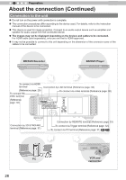
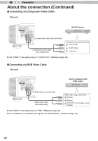
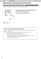
2 Preparation About the connection (Continued) ■ Connecting via Component Video Cable This unit STANDBY/ON INPUT OK C 1 HDMI 2 RS-232-C CR/PR CB/PB Y MENU BACK 3D SYNCHRO PC TRIGGER REMOTE CONTROL To component video input terminals Component video cable (sold separately) BD/DVD player Component video output terminals CR/PR (red) CB/PB (blue) Y (green) ● Set "COMP." in the setting menu to "Y Pb/Cb Pr/Cr". (Reference page: 60) ■ Connecting via RGB Video Cable This unit 1 HDMI 2 RS-232-C CR/PR CB/PB Y STANDBY/ON INPUT OK 3D SYNCHRO PC TRIGGER REMOTE CONTROL To RGB video MENU BACK input terminals RGB video cable (sold separately) Device equipped with RGB output RGB video output terminals R(Red) B(Blue) G(Green) (Includes sync signals) ● Set "COMP." in the setting menu to "RGB". (Reference page: 60) ● For information on compatible input signals, see "Specifications". (Reference page: 92) 30
-
 1
1 -
2
-
3
-
4
-
5
-
6
-
7
-
8
-
9
-
10
-
11
-
12
-
13
-
14
-
15
-
16
-
17
-
18
-
19
-
20
-
21
-
22
-
23
-
24
-
 25
25 -
 26
26 -
 27
27 -
 28
28 -
 29
29 -
 30
30 -
 31
31 -
 32
32 -
 33
33 -
 34
34 -
 35
35 -
36
-
37
-
38
-
39
-
40
-
41
-
42
-
43
-
44
-
45
-
46
-
47
-
48
-
49
-
50
-
51
-
52
-
53
-
54
-
55
-
56
-
57
-
58
-
59
-
60
-
61
-
62
-
63
-
64
-
65
-
66
-
67
-
68
-
69
-
70
-
71
-
72
-
73
-
74
-
75
-
76
-
77
-
78
-
79
-
80
-
81
-
82
-
83
-
84
-
85
-
86
-
87
-
88
-
89
-
90
-
91
-
92
-
93
-
94
-
95
-
96
 |
 |
