JVC GY-DV5000U GY-DV5000U 3-CCD Professional DV Camcorder 92 page instruction - Page 20
Preparations, 5- 1 Turning The Power On, Remaining Battery Power Display - gy dv5000 battery
 |
View all JVC GY-DV5000U manuals
Add to My Manuals
Save this manual to your list of manuals |
Page 20 highlights
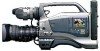
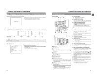
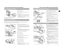
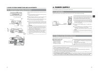
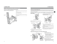
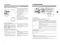
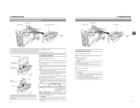
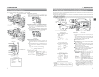
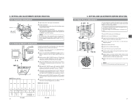
4. POWER SUPPLY 4-2 Battery Pack Operation (Optional) (Cont'd) REMAINING BATTERY POWER DISPLAY LCD monitor To display the remaining battery power accurately, set the BATTERY TYPE item on the OTHERS (2/2) menu screen in accordance with the type of the battery pack in use. ☞ See "BATTERY TYPE" on page 78. OPEN CH-1 AUDIO LEVEL CH-2 LCD BRIGHT FRONT REAR CH-1 CH-2 AUDIO INPUT AUDIO SELECT CH-1 CH-2 AUTO MANUAL DISPLAY PULL OPEN LOW VOLTAGE 10.5V TALLY lamp Battery lamp Viewfinder LOW VOLTAGE 10.5V REC BATT ALARM When the remaining battery power is nearly exhausted, the following warnings will be generated. ■ Viewfinder screen or LCD monitor When a Status screen is displayed (excluding the Status 2 screen in the Camera mode) ● Voltage indication: Blinks ● Alarm indication: LOW VOLTAGE displayed. ■ Viewfinder lamps BATT lamp and TALLY lamp: Blinks ■ BACK TALLY lamp on camera: Blinks ■ Monitoring loudspeaker and PHONES jack: Alarm sound After the remaining battery power warnings appear, the GY-DV5000 automatically stops operation if the battery power operation is continued. Operating Time with Battery Pack When the VF-P115B is used as the viewfinder and a fully charged battery pack is attached, the approximate continuous operating time is as follows: Battery Pack NP-1B Magnum 14 NP-L40 Continuous Operating Time (at 25 ˚C) 60 minutes 130 minutes 80 minutes ● Battery operating time may differ depending on the age of the battery, charging conditions and the operating environment, etc. Use the values in the table on the left for approximate reference times. ● Operating time is reduced in areas with a cold environment. ● Operating time is reduced when the power zoom lens and LCD are used frequently. PRECAUTIONS FOR THE BATTERY PACK ● When the battery pack is not in use, it must be stored in a cool, dry place. Do not leave the battery pack in a place where it might be subject to a high temperature (under direct sunlight in a car, etc.), this could cause leakage of the fluid or shorten service life. ● When the terminal section of the battery pack gets dirty, the operating time will be shortened. ● If the operating time becomes greatly reduced even immediately after recharging, the service life of the battery pack is nearly finished. Purchase a new battery pack. Recharging ● Recharge the battery pack after completely discharging it. Repeated recharging with residual charge remaining could result in reduced battery capacity. ● If the battery capacity is reduced by repeating incomplete recharging, or recharging without discharging, once discharge the battery pack completely, then recharge it to restore the battery capacity. ● If the battery pack is recharged with its internal temperature raised immediately after use, recharging may not be performed completely. 36 5. PREPARATIONS 5-1 Turning the Power ON EDITSEARCH FILTER 1 3200K 2 5600K 1/8 ND .3 5600K .4 5600K 1/64 ND SHUTTER STATUS MONITOR MENU AUTO IRIS FULL AUTO BACK L NORMAL SPOT L BLACK LOLUX STRETCH NORMAL COMPRESS MODE VTR CAM POWER VTR ON OFF OPEN CH-1 AUDIO LEVEL CH-2 LCD BRIGHT FRONT REAR CH-1 CH-2 AUDIO INPUT AUDIO SELECT CH-1 CH-2 AUTO MANUAL DISPLAY PULL OPEN MENU AUTO IRIS FULL AUTO BACK L NORMAL SPOT L BLACK LOLUX STRETCH NORMAL COMPRESS MODE VTR CAM POWER VTR ON OFF MODE POWER switch switch MODE indicator 1. Set the POWER switch to ON. The unit turns on in Camera mode. ■ The operation differs according to whether the unit is in the Camera mode or in the VTR mode. When the MODE switch is pressed upward, the mode is changed. The Camera indicator or VTR indicator comes on in accordance with the selected mode. Mode Camera mode Operation The GY-DV5000 enters the record mode. The camera image is displayed in the viewfinder or on the LCD monitor. When a recordable videocassette is loaded, the GY-DV5000 enters the record-standby mode automatically. "STBY" is displayed in the VTR operation mode indication area of the LCD monitor or in the viewfinder. In this condition, press the VTR trigger button to start recording. * Playback is also possible in the Camera mode. Playback operation becomes possible when the STOP button is pressed to set the VTR operation mode indicator to indicate STOP. VTR mode The GY-DV5000 enters the VTR playback mode. The camera image will not be displayed in the viewfinder or on the LCD monitor. When a videocassette is loaded, the GY-DV5000 enters the stop mode. "STOP" is displayed in the VTR operation mode indication area of the LCD monitor or in the viewfinder. Turning the Power OFF 1. Place the GY-DV5000 in the record-standby or STOP mode. 2. Set the POWER switch to OFF. 3. Remove the battery pack or the power supply to the DC IN connector. (When the camera is not going to be used for a longer period.) CAUTION: ● Do not set the POWER switch to OFF while recording is taking place. Confirm that the STBY or STOP indication is shown in the VTR operation mode indication area before the power is turned off. Should the POWER switch accidentally be set to OFF during a recording, wait at least 5 seconds before turning the power on again. ● Always set the POWER switch to OFF before disconnecting the power supply Do not turn the battery pack or AC power supply OFF while the POWER switch on the camera is still set to ON. 37
-
 1
1 -
2
-
3
-
4
-
5
-
6
-
7
-
8
-
9
-
10
-
11
-
12
-
13
-
14
-
 15
15 -
 16
16 -
 17
17 -
 18
18 -
 19
19 -
 20
20 -
 21
21 -
 22
22 -
 23
23 -
 24
24 -
 25
25 -
26
-
27
-
28
-
29
-
30
-
31
-
32
-
33
-
34
-
35
-
36
-
37
-
38
-
39
-
40
-
41
-
42
-
43
-
44
-
45
-
46
-
47
-
48
-
49
 |
 |