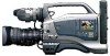
JVC GY-DV5000U GY-DV5000U 3-CCD Professional DV Camcorder 92 page instruction - Page 24
5 Charging the Built- in Battery, 6. SETTING AND ADJUSTMENTS BEFORE SHOOTING, 6- 1 Camera Settings - gy dv5000 dv
 |
View all JVC GY-DV5000U manuals
Add to My Manuals
Save this manual to your list of manuals |
Page 24 highlights
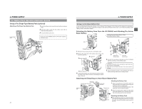
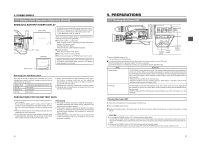
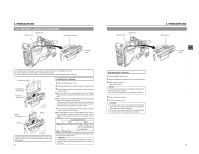
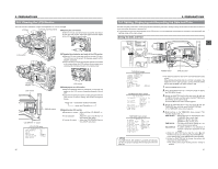
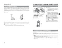
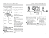
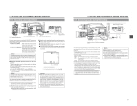
5. PREPARATIONS 5-5 Charging the Built-in Battery The built-in, rechargeable backup battery retains the date and time and the time code data. The built-in battery is constantly being charge whenever the GY-DV5000 is connected to a power supply, but it gradually discharges while the GY-DV5000 is disconnected from a power supply. The battery will be fully discharged when the GY-DV5000 is not used for about three months, in which case the set date and time and time code data are reset. In this case, recharge the built-in battery and then set the date and time and time code data again. However, it is possible to use the GY-DV5000 even if the bulit-in battery is discharged but the date and time and time code data cannot be recorded. ■ How to charge AC outlet AA-P250 AC power adapter DC cable PHONES DV REAR AUDIO IN DC OUT DC IN TALLY 1. Connect the provided AC adapter AA-P250 to the GY-DV5000 and an AC outlet or mount a charged battery on the GY-DV5000. 2. Set the POWER switch on the GY-DV5000 to "OFF" or "ON" (charging takes places with the POWER switch set to either of the positions.) 3. Leave the equipment in this condition for about 4 hours. ● The built-in battery will remain charged for about 3 months after being charged for about 4 hours. 44 6. SETTING AND ADJUSTMENTS BEFORE SHOOTING 6-1 Camera Settings 3. 2. EDITSEARCH FILTER 1 3200K 2 5600K 1/8 ND .3 5600K .4 5600K 1/64 ND SHUTTER STATUS MONITOR MENU AUTO IRIS FULL AUTO BACK L NORMAL SPOT L BLACK LOLUX STRETCH NORMAL COMPRESS MODE VTR CAM POWER VTR ON OFF OPEN CH-1 AUDIO LEVEL CH-2 LCD BRIGHT FRONT REAR CH-1 CH-2 AUDIO INPUT AUDIO SELECT CH-1 CH-2 AUTO MANUAL DISPLAY PULL OPEN 1. POWER VTR ON OFF CAM indicator GAIN HM L OUTPUT BARS CAM OFF ON AUTOKNEE WHT.BAL PRST A B MODE BCDA 1. POWER SUPPLY 1 First place a charged battery pack in the battery case on the rear section of the unit. If battery pack is not used, connect DC power to the DC INPUT connector on the rear section of the unit using the AC power adapter (AAP250) to supply DC 12 V current. 2 Set the POWER switch to ON. 2. SWITCH positions A. MODE switch: Camera mode (CAM indicator should be on). B. [GAIN] switch: Set to L. The L position is always 0 dB. C. [OUTPUT] switch: Set to CAM-AUTO KNEE OFF. D. [WHT. BAL] (Auto White Balance) switch: Set to A or B. 3. Set the lens' iris mode switch to "A" (AUTO IRIS side) 4. Choose the proper color temperature conversion filter. FILTER 1 3200K 2 5600K+1/8ND 3 5600K 4 5600K+1/64ND Suitable Location Indoors, dark outdoors Outdoors under clear sky Outdoors Outdoors under clear sky 5. Using the SHUTTER dial, set the shutter speed to OFF (1/60). VF 4. 5. OFF ZEBRA ON SKIN AREA AUTO WHITE ACCU FOCUS VTR AUDIO LEVELE CH-1 5 6-2 Screen Size (4:3/LETTER) Mode Selection The screen size of recorded images can be selected with the ASPECT RATIO item on the CAMERA OPERATION menu screen. ☞ See page 69. ● To record using the standard screen, set ASPECT RATIO to 4:3. ● When ASPECT RATIO is set to LETTER, the image is recorded in a 16:9 aspect ratio with the upper and lower parts of the image cut. In this case, the viewfinder screen or LCD will show the 16:9 aspect ratio image with the upper and lower parts of the image cut. MEMO: ● The safety zone of the standard screen and the 16:9 screen can be displayed in the viewfinder or LCD by setting the SAFETY ZONE item on the LCD/VF (1/2) menu screen. ☞ See page 73. ● When ASPECT RATIO is set to LETTER, 16:9 aspect ratio distinction ID signal is output from the Y/C OUT terminal. ● When setting DATE REC in the TIME/DATE menu screen to "BARS" or "BARS+CAM", the screen size will be fixed at an aspect ratio of 4:3. 45
-
 1
1 -
2
-
3
-
4
-
5
-
6
-
7
-
8
-
9
-
10
-
11
-
12
-
13
-
14
-
15
-
16
-
17
-
18
-
 19
19 -
 20
20 -
 21
21 -
 22
22 -
 23
23 -
 24
24 -
 25
25 -
 26
26 -
 27
27 -
 28
28 -
 29
29 -
30
-
31
-
32
-
33
-
34
-
35
-
36
-
37
-
38
-
39
-
40
-
41
-
42
-
43
-
44
-
45
-
46
-
47
-
48
-
49
 |
 |
