JVC GY-DV5000U GY-DV5000U 3-CCD Professional DV Camcorder 92 page instruction - Page 26
6 White Balance Adjustment, 6- 7 Audio Input Signal Selection, FULL-TIME AUTO WHITE BALANCE FAW
 |
View all JVC GY-DV5000U manuals
Add to My Manuals
Save this manual to your list of manuals |
Page 26 highlights
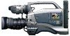
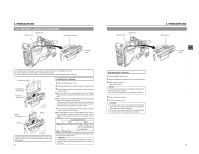
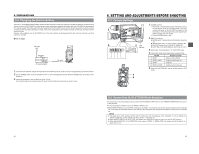
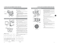
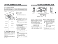
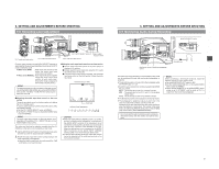
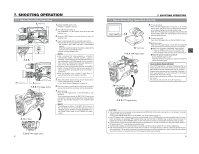
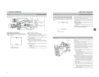
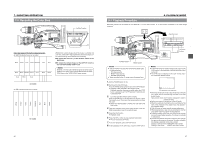
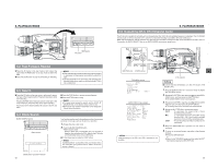
6. SETTING AND ADJUSTMENTS BEFORE SHOOTING 6-6 White Balance Adjustment Since the color of light (color temperature) varies depending on the light source, it is necessary to re-adjust the white balance when the main light source illuminating the subject changes. Note When a subject illuminated by a halogen lamp with a color temperature of 3,200K is shot while the color temperature conversion filter setting is set to 5,600K, 5,600K+1/8 ND, or 5,600K+1/64 ND, a proper white balance adjustment and (FAW) Full Time Auto White balance may not be accomplishable. In this case, change the color temperature conversion filter setting to 3,200K and then carry out the white balance adjustment and (FAW) again. ● Do not adjust using any highly reflective objects, such as metal, etc., as this may result in improper white balance adjustment. WHITE BALANCE ADJUSTMENT 2. FILTER knob 1. Iris mode switch 5. AUTO WHT. /ACCU FOCUS switch 3. WHT.BAL switch 1. OUTPUT switch 1. POWER switch AUTO WHITE A OPERATION During operation AUTO WHITE A OK Result message AUTO WHITE A NG:OBJECT Improper object AUTO WHITE A ERROR:LOW LIGHT Insufficient illumination AUTO WHITE A ERROR:OVER LIGHT Excessive illumination FULL-TIME AUTO WHITE BALANCE (FAW) The FAW function adjusts the white balance value automatically as the lighting condition changes. This mode is convenient when you have no time to adjust the white balance or when the camera is moved frequently in and out of places under different lighting conditions. ■ Setting procedure The FAW function can be activated with the FAW item on the CAMERA OPERATION menu screen. The FAW function can be allocated to one of the white balance switching switches A, B, or PRESET. ☞ See "CAMERA OPERATION menu screen" on page 69. Two kinds of white balance adjustment results can be stored in memories AUTO1 and AUTO2. Ⅲ Adjustment procedure 1. Set the following switches. ● Set the POWER switch to ON. ● Set the OUTPUT switch to CAM-AUTO KNEE. ● Set the IRIS mode switch of the lens to A (Auto). 2. Set the FILTER knob according to the current lighting. 3. Set the WHT.BAL switch to A or B. 4. Place a white object near the centre of the screen under the same lighting conditions as the target subject and zoom in to fill the screen with white. 5. Tilt the AUTO WHT./ACCU FOCUS switch upward (to AUTO WHITE) once and release it. "AUTO WHITE A, B OPERATION" is displayed in the viewfinder while the auto white balance adjustment circuit operates. When correct white balance is obtained, the approximate color temperature is displayed together with "AUTO WHITE A, B OK" for about 5 seconds. Error messages If the adjustment ends abnormally, an error message, as described below, blinks for about 5 seconds. ● NG: OBJECT (Improper object) Displayed when there is not enough white color on an object or the color temperature is not suitable. Replace the color temperature conversion filter or use another white object and re-adjust the white balance. ● ERROR: LOW LIGHT (Insufficient illumination) Displayed when the illumination is dim. Increase the illumination and then re-adjust the white balance. ● ERROR: OVER LIGHT (Excessive illumination) Displayed when the light is excessively bright. Decrease the illumination and then re-adjust the white balance. CAUTION: ● The FAW (Full-time Auto White balance) function cannot provide optimum white balance with a subject outside the FAW adjustment range, for example when it contains only a single color or not enough white color. ● The accuracy of the FAW (Full-time Auto White balance) is inferior to that of the manual white balance. ● When the power is turned on with the FAW mode selected, it takes about 10 seconds for the FAW adjustment to be completed. Do not shoot within this interval. 48 6. SETTING AND ADJUSTMENTS BEFORE SHOOTING 6-7 Audio Input Signal Selection VF OFF ZEBRA ON SKIN AREA AUTO WHITE ACCU FOCUS VTR AUDIO LEVELE CH-1 5 FRONT AUDIO IN connector EDITSEARCH FILTER 1 3200K 2 5600K 1/8 ND .3 5600K .4 5600K 1/64 ND SHUTTER STATUS MONITOR MENU AUTO IRIS FULL AUTO BACK L NORMAL SPOT L BLACK LOLUX STRETCH NORMAL COMPRESS MODE VTR CAM POWER VTR ON OFF OPEN CH-1 AUDIO LEVEL CH-2 LCD BRIGHT FRONT REAR CH-1 CH-2 AUDIO INPUT AUDIO SELECT CH-1 CH-2 AUTO MANUAL DISPLAY PULL OPEN CH-1 AUDIO INPUT switch CH-2 AUDIO INPUT LCD BRIGHT DISPLAY switch AUDIO INPUT (LINE/MIC) switch CH-1 AUDIO LEVEL CH-2 MONITOR SELECT CH-1 MIX CH-2 AUDIO INPUT FRONT REAR LINE MIC +48V FRONT REAR CH-1 CH-2 AUDIO INPUT AUDIO SELECT CH-1 CH-2 AUTO MANUAL COUNTER TC UB TC GENE. REGEN FREE REC PRST PHONES DV REAR AUDIO IN DC OUT DC IN TALLY REAR AUDIO IN connector The GY-DV5000 is provided with the FRONT AUDIO IN connector and the REAR AUDIO IN connector for audio input. Two channels of sound can be recorded on the tape in digital PCM format. Using the AUDIO INPUT switch, select for each channel (CH1 and CH2) whether the sound to be recorded should be the sound from the FRONT AUDIO IN connector or the sound from the REAR AUDIO IN connector. ■ Selecting the CH-1 channel input sound Make the selection using the CH-1 AUDIO INPUT switch. FRONT : The sound from the FRONT AUDIO IN connector is recorded on the CH-1 channel. REAR : The sound from the REAR AUDIO IN connector is recorded on the CH-1 channel. ■ Selecting the CH-2 channel input sound Make the selection using the CH-2 AUDIO INPUT switch. FRONT : The sound from the FRONT AUDIO IN connector is recorded on the CH-2 channel. REAR : The sound from the REAR AUDIO IN connector is recorded on the CH-2 channel. ■ Selecting the FRONT AUDIO IN connector and REAR AUDIO IN connector Select the sound to be input to the AUDIO INPUT connector using the AUDIO INPUT (LINE/MIC) switch. The setting is made individually for both the FRONT AUDIO IN connector and the REAR AUDIO IN connector. LINE : Set to this position when connected to audio equipment, etc. The reference input level is +4 dBs. MIC : Set to this position when using a monaural microphone. The reference input level is -60 dBs. +48 V : Set to this position when a microphone (phantom microphone) requiring +48 V DC power supply is connected. CAUTION: Before connecting a component that does not require +48 V power supply, make sure that the AUDIO INPUT (LINE/ MIC) switch is not set to +48 V. Neglecting this could cause damage to the connected component. 49
-
 1
1 -
2
-
3
-
4
-
5
-
6
-
7
-
8
-
9
-
10
-
11
-
12
-
13
-
14
-
15
-
16
-
17
-
18
-
19
-
20
-
 21
21 -
 22
22 -
 23
23 -
 24
24 -
 25
25 -
 26
26 -
 27
27 -
 28
28 -
 29
29 -
 30
30 -
 31
31 -
32
-
33
-
34
-
35
-
36
-
37
-
38
-
39
-
40
-
41
-
42
-
43
-
44
-
45
-
46
-
47
-
48
-
49
 |
 |