JVC TK-WD310U Instructions - Page 23
Power supply DC 12 V or AC 24 V, Do not allow input from both a DC 12 V and AC 24 V power
 |
UPC - 046838007972
View all JVC TK-WD310U manuals
Add to My Manuals
Save this manual to your list of manuals |
Page 23 highlights
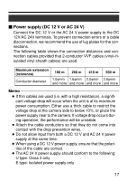
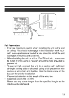
Ⅵ Power supply (DC 12 V or AC 24 V) Connect the DC 12 V or the AC 24 V power supply to the DC 12V/AC 24V terminals. To prevent connection errors or a cable disconnection, we recommend the use of lug plates for the connections. The following table shows the connection distances and connection cables provided that 2-conductor VVF cables (vinyl-insulated vinyl sheath cables) are used. Maximum extension (reference) Conductor diameter 100 m 260 m 410 m 500 m 1.0φmm 1.6φmm 2.0φmm 2.6φmm and more and more and more and more Memo ● If thin cables are used (i.e. with a high resistance), a significant voltage drop will occur when the unit is at its maximum power consumption. Either use a thick cable to restrict the voltage drop at the camera side to below 10%, or place the power supply near to the camera. If voltage drop occurs during operation, the performance will be unstable. ● Attach the cable conductors so that they do not come into contact with the drop prevention wires. ● Do not allow input from both a DC 12 V and AC 24 V power supply at the same time. ● When using a DC 12 V power supply, ensure that the polarities of the cable are correct. ● The AC 24 V power supply should conform to the following: U type: Class 2 only E type: Isolated power supply only 17
-
 1
1 -
2
-
3
-
4
-
5
-
6
-
7
-
8
-
9
-
10
-
11
-
12
-
13
-
14
-
15
-
16
-
17
-
 18
18 -
 19
19 -
 20
20 -
 21
21 -
 22
22 -
 23
23 -
 24
24 -
 25
25 -
 26
26 -
 27
27 -
 28
28 -
29
-
30
-
31
-
32
-
33
-
34
-
35
-
36
-
37
-
38
-
39
-
40
-
41
-
42
-
43
-
44
-
45
-
46
-
47
-
48
 |
 |
