JVC TM-1650SDU TM-1650SDU monitor instruction manual (358KB) - Page 4
Controls And Features
 |
View all JVC TM-1650SDU manuals
Add to My Manuals
Save this manual to your list of manuals |
Page 4 highlights
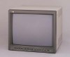
CONTROLS AND FEATURES FRONT VIEW 19 TM-1650SDU PHASE CHROMA BRIGHT CONTRAST MENU - + VOLUME/SELECT UNDER RGB/COMPO./ SCAN SDI B Y/ C VIDEO A VIDEO INPUT SELECT POWER ON STAND BY 1 2 34 5 TM-1650SDU PHASE CHROMA BRIGHT CONTRAST MENU 6 - + VOLUME/SELECT 7 8 9 10 11 12 13 UNDER RGB/COMPO./ SCAN SDI B Y/ C VIDEO A VIDEO INPUT SELECT POWER ON STAND BY 14 15 16 17 18 1 Phase button [PHASE ] Press this button to set the picture hue adjustment mode. Adjust the value with the VOLUME/SELECT buttons. Also used as a control button in the menu function mode. 2 Chroma button [CHROMA ] Press this button to set the picture color density adjustment mode. Adjust the value with the VOLUME/SELECT buttons. Also used as a control button in the menu function mode. 3 Brightness button [BRIGHT ] Press this button to adjust picture brightness. Adjust the value with the VOLUME/SELECT buttons. Also used as a control button in the menu function mode. 4 Contrast button [CONTRAST ] Press this button to adjust picture contrast. Adjust the value with the VOLUME/SELECT buttons. Also used as a control button in the menu function mode. 5 Menu button [MENU] Displays and disappears the screen. Pressing the PHASE button with the Menu button depressed will display the screen. 6 Volume/Select buttons [VOLUME/ SELECT - +] Adjusts the speaker volume. Also used as a control button in the menu function mode. 7 Under Scan button [UNDER SCAN] Reduces the screen size to display the whole screen. Press the button again to quit Under Scan. 8 Input RGB/COMPO./SDI button [INPUT SELECT RGB/COMPO./SDI ] Selects the video signal input to the RGB/COMPO. (analog RGB/Y, B-Y, R-Y) or SDI terminal and the audio signal input to the AUDIO RGB/COMPO./SDI terminal on the rear panel. When selected, the input RGB/COMPO./ SDI indicator % lights. Note: ● RGB, COMPONENT or SDI signals can be selected in the screen. 9 Input B (Y/C) button [INPUT SELECT B Y/C ] Selects the video signal input to the VIDEO B (Y/C) terminal and the audio signal input to the AUDIO B terminal on the rear panel. When selected, the input B (Y/C) indicator ^ lights. 10 Input B (VIDEO) button [INPUT SELECT B VIDEO ] Selects the video signal input to the VIDEO B terminal and the audio signal input to the AUDIO B terminal on the rear panel. When selected, the input B (VIDEO) indicator & lights. 11 Input A (VIDEO) button [INPUT SELECT A VIDEO ] Selects the video signal input to the VIDEO A terminal and the audio signal input to the AUDIO A terminal on the rear panel. When selected, the input A (VIDEO) indicator * lights. 12 Power indicator Lights in green when the power is ON. Lit : When the power is on. Unlit : When the power is set to stand-by. 13 Power switch [POWER] Press this switch to turn the power on or set it to stand-by mode. ON : Power is turned on. STAND BY : Power is set to stand-by mode. 14 UNDER SCAN indicator Lights in green when UNDER SCAN is selected. 15 Input RGB/COMPO./SDI indicator Lights in green when Input RGB/COMPO./SDI is selected. 16 Input B (Y/C) indicator Lights in green when Input B (Y/C) is selected. 17 Input B (VIDEO) indicator Lights in green when Input B (VIDEO) is selected. 18 Input A (VIDEO) indicator Lights in green when Input A (VIDEO) is selected. 19 Speaker A built-in speaker is located inside the right side panel when the monitor is viewed from the front. 4
-
 1
1 -
 2
2 -
 3
3 -
 4
4 -
 5
5 -
 6
6 -
 7
7 -
 8
8 -
 9
9 -
 10
10 -
11
-
12
-
13
-
14
-
15
-
16
-
17
-
18
-
19
-
20
 |
 |
