JVC TMH-150CGU Instruction Manual - Page 7
Rear Panel, cont'd
 |
UPC - 046838010682
View all JVC TMH-150CGU manuals
Add to My Manuals
Save this manual to your list of manuals |
Page 7 highlights
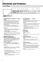
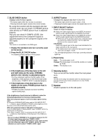
Controls and Features (cont'd) Rear Panel e r t y u i o ; REMOTE SLOT MAKE/ TRIGGER POWER a e VIDEO A terminal Input (IN) and output (OUT) terminals for composite signals. • The IN and OUT terminals are bridge-connected (auto termination). NOTE: Use the AUDIO A terminals for the corresponding audio signals. r VIDEO B terminal Input (IN) and output (OUT) terminals for composite signals. • The IN and OUT terminals are bridge-connected (auto termination). NOTE: Use the AUDIO B terminals for the corresponding audio signals. t VIDEO B (Y/C IN,Y/C OUT) terminal Input (IN) and output (OUT) terminals for Y/C (Svideo) signals. • The Y/C IN and Y/C OUT terminals are bridge-connected (auto termination). NOTES: • Use the AUDIO B terminals for the corresponding audio signals. • When both an Y/C (S-video) signal and a composite signal are input to the VIDEO B terminal, the Y/C signal has priority over the composite signal. y AUDIO A terminal Input (IN) and output (OUT) terminals for analog audio signals. • The IN and OUT terminals are bridge-connected (auto termination). NOTE: Use the VIDEO A terminals for the corresponding video signals. u AUDIO B terminal Input (IN) and output (OUT) terminals for analog audio signals. • The IN and OUT terminals are bridge-connected (auto termination). NOTE: Use the VIDEO B terminals for the corresponding video signals. i Input card slot When using the input card (not supplied), install the card to this slot. o REMOTE (external control) terminal Terminals for controlling the monitor by an external control. \ For details, see page 15. ; Main power switch Turns on and off the main power. • I: ON ‡: OFF NOTE: When turning on the main power, the power lamp lights up as follows: • Orange: The monitor is in stand-by mode. • Green: The monitor is on. a AC inlet Connect the supplied AC power cord to this inlet and an AC outlet (120 V AC/220 - 240 V AC, 50 Hz/ 60 Hz). 6
-
 1
1 -
 2
2 -
 3
3 -
 4
4 -
 5
5 -
 6
6 -
 7
7 -
 8
8 -
 9
9 -
 10
10 -
 11
11 -
 12
12 -
13
-
14
-
15
-
16
-
17
-
18
-
19
-
20
-
21
 |
 |
