Jenn-Air JDRP436HL Installation Instructions - Page 12
Install Anti-Tip Bracket
 |
View all Jenn-Air JDRP436HL manuals
Add to My Manuals
Save this manual to your list of manuals |
Page 12 highlights
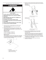
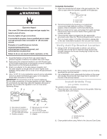
Install Anti-Tip Bracket WARNING 3. Drill two 1/8" (3.0 mm) holes that correspond to the bracket holes of the determined mounting method. See the following illustrations. Floor Mounting B A Tip Over Hazard A child or adult can tip the range and be killed. Install anti-tip bracket to floor or wall per installation instructions. Slide range back so rear range foot is engaged in the slot of the anti-tip bracket. Re-engage anti-tip bracket if range is moved. Do not operate range without anti-tip bracket installed and engaged. Failure to follow these instructions can result in death or serious burns to children and adults. 1. Determine which mounting method to use: floor or wall. If you have a stone or masonry floor, you can use the wall mounting method. 2. Determine and mark centerline of the cutout space. The mounting bracket must be installed on the left side of the cutout. Position mounting bracket in cutout as shown in the following illustration. Measurement B: 30" (76.2 cm) ranges: 13" (33.0 cm) 36" (91.4 cm) ranges: 16" (40.6 cm) 48" (121.9 cm) ranges: 22" (55.9 cm) Measurement C: Optional distance from back wall. If back wall is constructed of a combustible material and a backguard is not installed, a 6" (15.2 cm) minimum clearance is required for all models. Install anti-tip bracket accordingly. C A A. #12 x 15⁄8" (4.1 cm) screws B. Anti-tip bracket Wall Mounting B A A. #12 x 15⁄8" (4.1 cm) screws B. Anti-tip bracket 4. Using a Phillips screwdriver, mount anti-tip bracket to the wall or floor with the two #12 x 15⁄8" (4.1 cm) screws provided. Depending on the thickness of your flooring, longer screws may be necessary to anchor the bracket to the subfloor. Longer screws are available from your local hardware store. 5. Move range close enough to opening to allow for electrical connections to be made. Remove shipping base, cardboard, or hardboard from under range. 6. Continue installing your range using the following installation instructions. B A. Centerline B. Centerline of cutout to outside edge of anti-tip bracket C. Back wall to back of range 12
-
 1
1 -
2
-
3
-
4
-
5
-
6
-
 7
7 -
 8
8 -
 9
9 -
 10
10 -
 11
11 -
 12
12 -
 13
13 -
 14
14 -
 15
15 -
 16
16 -
 17
17 -
18
-
19
-
20
-
21
-
22
-
23
-
24
-
25
-
26
-
27
-
28
-
29
-
30
-
31
-
32
-
33
-
34
-
35
-
36
-
37
-
38
-
39
-
40
-
41
-
42
-
43
-
44
-
45
-
46
-
47
-
48
 |
 |
