Jenn-Air JDRP436HL Installation Instructions - Page 13
Make Gas Connection, Verify Anti-Tip Bracket Location, Install Griddle Tray
 |
View all Jenn-Air JDRP436HL manuals
Add to My Manuals
Save this manual to your list of manuals |
Page 13 highlights
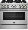
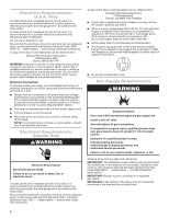
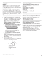
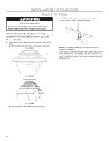
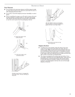
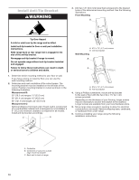
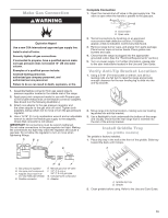
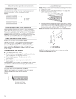
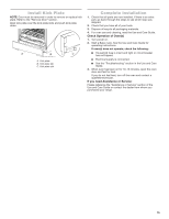
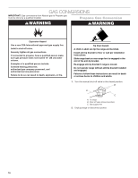
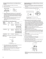
Make Gas Connection WARNING Complete Connection 1. Open the manual shut-off valve in the gas supply line. The valve is open when the handle is parallel to the gas pipe. A B Explosion Hazard Use a new CSA International approved gas supply line. Install a shut-off valve. Securely tighten all gas connections. If connected to propane, have a qualified person make sure gas pressure does not exceed 14" (36 cm) water column. Examples of a qualified person include: licensed heating personnel, authorized gas company personnel, and authorized service personnel. Failure to do so can result in death, explosion, or fire. 1. Assemble flexible connector from gas supply pipe to pressure regulator located in the middle rear of the range. 2. Apply pipe-joint compound made for use with Propane gas to the smaller thread ends of the flexible connector adapters. (See B and G in the following illustration.) 3. Attach one adapter to the gas pressure regulator and the other adapter to the gas shut-off valve. Tighten both adapters, being certain not to move or turn the gas pressure regulator. 4. Use a 15/16" (2.4 cm) combination wrench and an adjustable wrench to attach the flexible gas supply to the adapters. Check that connector is not kinked. IMPORTANT: All connections must be wrench-tightened. Do not make connections to the gas regulator too tight. Making the connections too tight may crack the regulator and cause a gas leak. Do not allow the regulator to turn or move when tightening fittings. A BC D E A. Closed valve B. Open valve 2. Test all connections by brushing on an approved noncorrosive leak-detection solution. If bubbles appear, a leak is indicated. Correct any leak found. 3. Remove range burner caps, and grates from parts package. Place burner caps on burner bases. Place grates over burners and caps. 4. Check that the range is plugged into the appropriate grounded outlet. (See the "Electrical Requirements" section.) 5. Turn on power supply. For further information, please refer to the user instructions located in the Use and Care Guide. Verify Anti-Tip Bracket Location 1. Using a 5/16" (7.9 mm) socket or wrench, turn all four leveling rods one full turn to raise the range and provide enough clearance for the rear leveling leg to slide into the anti-tip bracket. � 2. Move range into its final location, making sure rear leveling leg slides into anti-tip bracket. 3. Use a flashlight to look underneath the bottom of the range and visually check that the rear range foot is inserted into the slot of the anti-tip bracket. Install Griddle Tray (on griddle models) The griddle is factory installed. 1. Place drip tray in the well at the front of the griddle. Slide tray toward the back until it stops. A A. Gas pressure regulator B. Use pipe-joint compound. C. Adapter (must have 1/2" [1.3 cm] male pipe thread) D. Flexible connector HG F E. Manual gas shut-off valve F. 1/2" (1.3 cm) or 3/4" (1.9 cm) gas pipe G. Use pipe-joint compound. H. Adapter B A. Griddle drip tray B. Griddle 2. Clean griddle before using. Refer to the Use and Care Guide. 13
-
 1
1 -
2
-
3
-
4
-
5
-
6
-
7
-
 8
8 -
 9
9 -
 10
10 -
 11
11 -
 12
12 -
 13
13 -
 14
14 -
 15
15 -
 16
16 -
 17
17 -
 18
18 -
19
-
20
-
21
-
22
-
23
-
24
-
25
-
26
-
27
-
28
-
29
-
30
-
31
-
32
-
33
-
34
-
35
-
36
-
37
-
38
-
39
-
40
-
41
-
42
-
43
-
44
-
45
-
46
-
47
-
48
 |
 |