Kenmore 4689 Installation Instructions - Page 11
Anti-Tip, Brackets
 |
View all Kenmore 4689 manuals
Add to My Manuals
Save this manual to your list of manuals |
Page 11 highlights
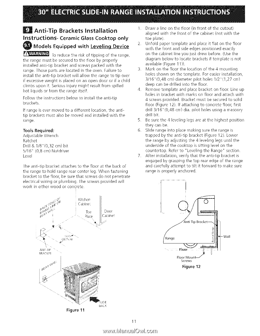
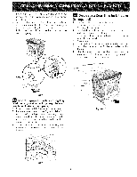
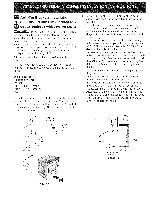
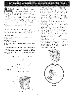
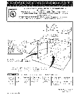
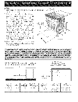
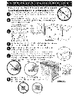
| Anti-Tip instructions- Brackets Installation Ceramic Glass Cooktop only Models Equipped with Leveling Device To reduce the risk of tipping of the range, the range must be secured to the floor by properly installed anti-tip bracket and screws packed with the range. Those parts are located in the oven. Failure to install the anti-tip bracket will allow the range to tip over if excessive weight is placed on an open door or if a child climbs upon it. Serious injury might result from spilled hot liquids or from the range itself. Follow the instructions below to install the anti-tip brackets. If range is ever moved to a different location, the antitip brackets must also be moved and installed with the range. Tools Required: Adjustable Wrench Ratchet Drill & 1/8"(0,32 cm) bit 5/16" (0,8 cm) Nutdriver Level The anti-tip bracket attaches to the floor at the back of the range to hold range rear center leg. When fastening bracket to the floor, be sure that screws do not penetrate electrical wiring or plumbing. The screws provided will work in either wood or concrete. 1. Draw a line on the floor (in front of the cutout) aligned with the front of the cabinet (not with the toe plate). 2. Unfold paper template and place it flat on the floor with the front and side edges positioned exactly on the cabinet line you just drew before. (Use the diagram below to locate brackets if template is not available (Figure 11 )). 3. Mark on the floor the location of the 4 mounting holes shown on the template. For easier installation, 3/16"(0,48 cm) diameter pilot holes 1/2"(1,27 cm) deep can be drilled into the floor. 4. Remove template and place bracket on floor. Line up holes in bracket with marks on floor and attach with 4 screws provided. Bracket must be secured to solid floor (Figure 12). If attaching to concrete floor, first drill 3/16"(0,48 cm) dia. pilot holes using a masonry drill bit. 5. Be sure the 4 leveling legs are at the highest position they can be. 6. Slide range into place making sure the range is trapped by the anti-tip bracket (Figure 12). Lower the range by adjusting the 4 leveling legs until the underside of the cooktop is sitting level on the countertop. Refer to "Leveling the Range" section. 7. After installation, verify that the anti-tip bracket is engaged by grasping the top rear edge of the range and carefully attempt to tilt it forward to make sure range is properly anchored. ¢0d,_ Adl
-
 1
1 -
2
-
3
-
4
-
5
-
 6
6 -
 7
7 -
 8
8 -
 9
9 -
 10
10 -
 11
11 -
 12
12 -
 13
13 -
 14
14 -
 15
15 -
 16
16 -
17
-
18
-
19
-
20
-
21
-
22
-
23
-
24
 |
 |