Kenmore 4689 Installation Instructions - Page 6
Cord Kit Hole.
 |
View all Kenmore 4689 manuals
Add to My Manuals
Save this manual to your list of manuals |
Page 6 highlights
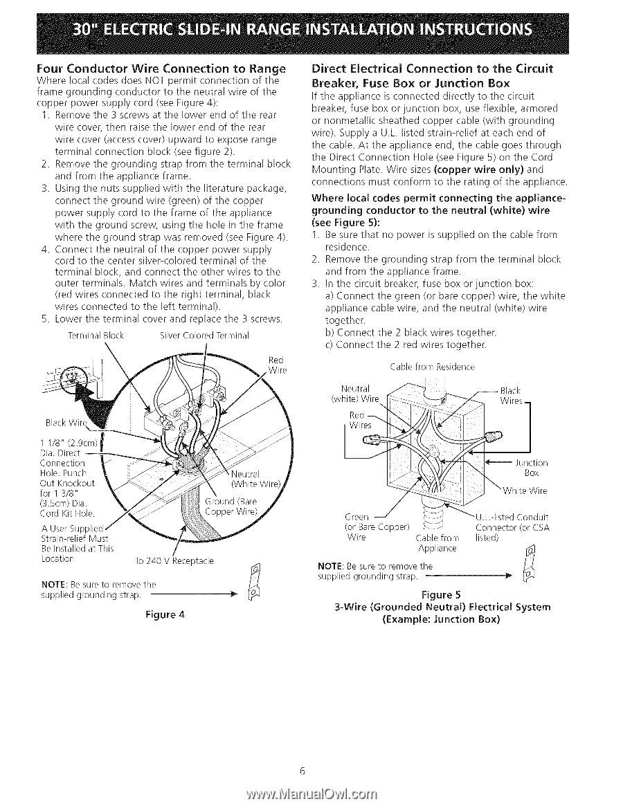
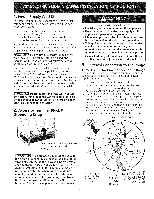
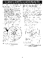
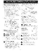
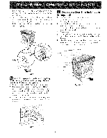
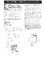
Four Conductor Wire Connection to Range Where local codes does NOT permit connection of the frame grounding conductor to the neutral wire of the copper power supply cord (see Figure 4): 1. Remove the 3 screws at the lower end of the rear wire cover, then raise the lower end of the rear wire cover (access cover) upward to expose range terminal connection block (see figure 2). 2. Remove the grounding strap from the terminal block and from the appliance frame. 3. Using the nuts supplied with the literature package, connect the ground wire (green) of the copper power supply cord to the frame of the appliance with the ground screw, using the hole in the frame where the ground strap was removed (see Figure 4). 4. Connect the neutral of the copper power supply cord to the center silver-colored terminal of the terminal block, and connect the other wires to the outer terminals. Match wires and terminals by color (red wires connected to the right terminal, black wires connected to the left terminal). 5. Lower the terminal cover and replace the 3 screws. Terminal Block SilverColoredTerminal Red .Wire Direct Electrical Connection to the Circuit Breaker, Fuse Box or Junction Box If the appliance is connected directly to the circuit breaker, fuse box or junction box, use flexible, armored or nonmetallic sheathed copper cable (with grounding wire). Supply a U.L. listed strain-relief at each end of the cable. At the appliance end, the cable goes through the Direct Connection Hole (see Figure 5) on the Cord Mounting Plate. Wire sizes (copper wire only) and connections must conform to the rating of the appliance. Where local codes permit connecting the appliancegrounding conductor to the neutral (white) wire (see Figure 5): 1. Be sure that no power is supplied on the cable from residence. 2. Remove the grounding strap from the terminal block and from the appliance frame. 3. In the circuit breaker, fuse box or junction box: a) Connect the green (or bare copper) wire, the white appliance cable wire, and the neutral (white) wire together. b) Connect the 2 black wires together. c) Connect the 2 red wires together. Cable from Residence BlackWire 1 1/8" (2.9cm) f Dia. Direct m Connection Hole. Punch Out Knockout for 1 3/8" (3.5cm) Dia. Cord Kit Hole. A User Supplied Strain-relief Must Be Installed at This Location To 240 V Receptacle NOTE: Be sure to remove the supplied grounding strap. Figure 4 NOTE: Be sure to remove the supplied grounding strap. Figure 5 3-Wire (Grounded Neutral) Electrical System (Example: Junction Box)
-
 1
1 -
 2
2 -
 3
3 -
 4
4 -
 5
5 -
 6
6 -
 7
7 -
 8
8 -
 9
9 -
 10
10 -
 11
11 -
 12
12 -
13
-
14
-
15
-
16
-
17
-
18
-
19
-
20
-
21
-
22
-
23
-
24
 |
 |