Kenmore 9961 Installation Instructions - Page 4
Remove, the3loosenutsafteryouremoved, rubberbandontheterminal, blockusing3/8nut, driverorsocket.
 |
View all Kenmore 9961 manuals
Add to My Manuals
Save this manual to your list of manuals |
Page 4 highlights
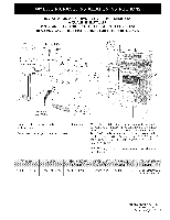
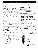
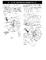
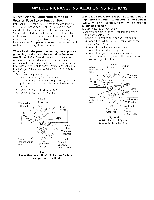
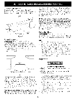
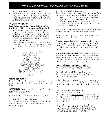
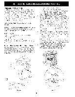
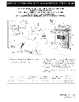
2. Removtehe 3 loosenuts(afteryouremovedthe rubberband)ontheterminabl lockusing3/8" nut driveror socket. 3. Connect the neutral white wire of the copper power supply cord to the center silver-colored terminal of the terminal block, and connect the other wires to the outer terminals. Match wires and terminals by color (red wires connected to the right terminal, black wires connected to the left terminal). 4. Replace the 3 nuts on the terminal block (see figure 3). 5. Lower the terminal cover and replace the 3 screws. Silver colored Terminal Terminal Block Black wire Four Conductor Wire Connection to Range (mobile homes) 1. Remove the 3 screws at the lower end of the rear wire cover, then raise the lower end of the rear wire cover (access cover) upward to expose range terminal connection block (see figure 2). 2. Remove the three loose nuts (after you removed the rubber band) on the terminal block using a 3/8" nut driver or socket. 3. Remove the grounding strap from the terminal block and from the appliance frame. 4. Connect the ground wire (green) of the copper power supply cord to the frame of the appliance with the ground screw, using the hole in the frame where the ground strap was removed (see Figure 4). 5. Connect the neutral of the copper power supply cord to the center silver-colored terminal of the terminal block, and connect the other wires to the outer terminals. Match wires and terminals by color (red wires connected to the right terminal, black wires connected to the left terminal). 6. Replace the 3 nuts on the terminal block (see figure 4). 7. Lower the terminal cover and replace the 3 screws. Block Silver Colored Terminal A strainreJief supplied by the user must be installed at this location 240 V receptade Figure 3 1-1/8" Dia. Direct Connection Hole. Punch out knockout for 1-3/8" Dia. Cord Kit Hole 1-1/8" Dia. Direct Connection Hole. Punch out knockout for !-3/8" Dia. Cord Kit Hole A user supplied strain-relief must be installed V receptacle aNtOtThEis; loBceatsiounre to remove the supplie I_J_t grounding strap Figure 4 4
-
 1
1 -
 2
2 -
 3
3 -
 4
4 -
 5
5 -
 6
6 -
 7
7 -
 8
8 -
 9
9 -
 10
10 -
11
-
12
-
13
-
14
-
15
-
16
 |
 |
