Kenmore 9961 Installation Instructions - Page 8
Important, Warning, Anti-Tip, Brackets, Installation, Instructions
 |
View all Kenmore 9961 manuals
Add to My Manuals
Save this manual to your list of manuals |
Page 8 highlights
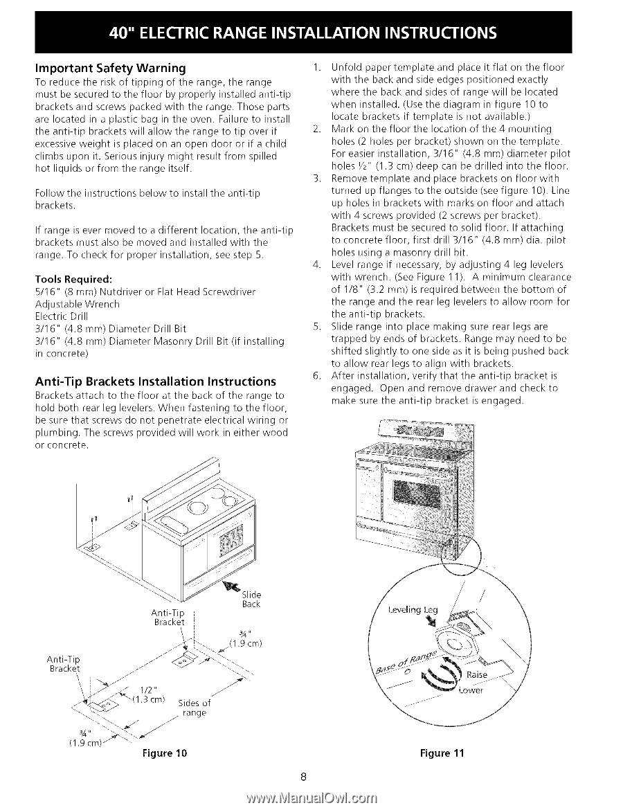
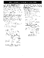
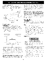
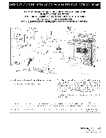
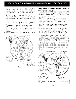
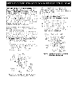
Important Safety Warning To reduce the risk of tipping of the range, the range must be secured to the floor by properly installed anti-tip brackets and screws packed with the range. Those parts are located in a plastic bag in the oven. Failure to install the anti-tip brackets will allow the range to tip over if excessive weight is placed on an open door or if a child climbs upon it. Serious injury might result from spilled hot liquids or from the range itself. Follow the instructions below to install the anti-tip brackets. If range is ever moved to a different location, the anti-tip brackets must also be moved and installed with the range. To check for proper installation, see step 5. Tools Required: 5/16" (8 mm) Nutdriver or Flat Head Screwdriver Adjustable Wrench Electric Drill 3/16" (4.8 mm) Diameter Drill Bit 3/16" (4.8 mm) Diameter Masonry Drill Bit (if installing in concrete) Anti-Tip Brackets Installation Instructions Brackets attach to the floor at the back of the range to hold both rear leg levelers. When fastening to the floor, be sure that screws do not penetrate electrical wiring or plumbing. The screws provided will work in either wood or concrete. 1. Unfold paper template and place it flat on the floor with the back and side edges positioned exactly where the back and sides of range will be located when installed. (Use the diagram in figure 10 to locate brackets if template is not available.) 2. Mark on the floor the location of the 4 mounting holes (2 holes per bracket) shown on the template. For easier installation, 3/16" (4.8 mm) diameter pilot holes Y2" (1.3 cm) deep can be drilled into the floor. 3. Remove template and place brackets on floor with turned up flanges to the outside (see figure 10). Line up holes in brackets with marks on floor and attach with 4 screws provided (2 screws per bracket). Brackets must be secured to solid floor. If attaching to concrete floor, first drill 3/16" (4.8 mm) dia. pilot holes using a masonry drill bit. 4. Level range if necessary, by adjusting 4 leg levelers with wrench. (See Figure 11). A minimum clearance of 1/8" (3.2 mm) is required between the bottom of the range and the rear leg levelers to allow room for the anti-tip brackets. 5. Slide range into place making sure rear legs are trapped by ends of brackets. Range may need to be shifted slightly to one side as it is being pushed back to allow rear legs to align with brackets. 6. After installation, verify that the anti-tip bracket is engaged. Open and remove drawer and check to make sure the anti-tip bracket is engaged. Figure 11
-
 1
1 -
2
-
 3
3 -
 4
4 -
 5
5 -
 6
6 -
 7
7 -
 8
8 -
 9
9 -
 10
10 -
 11
11 -
 12
12 -
 13
13 -
14
-
15
-
16
 |
 |