Kenwood KMR-M505DAB Instruction Manual - Page 39
Wiring connection
 |
View all Kenwood KMR-M505DAB manuals
Add to My Manuals
Save this manual to your list of manuals |
Page 39 highlights
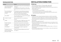
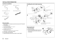
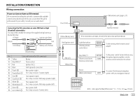
INSTALLATION/CONNECTION Wiring connection If your car does not have an ISO terminal: We recommend installing the unit with a commercially available custom wiring harness specific for your car and leave this job to professionals for your safety. Consult your car audio dealer. Connecting the ISO connectors on some VW/Audi or Opel (Vauxhall) automobiles You may need to modify the wiring of the supplied wiring harness as illustrated below. A7 (Red) Ignition wire (Red) Vehicle Unit A4 (Yellow) Battery wire (Yellow) Default wiring Pin Color and function (for ISO connectors) A4 Yellow : Battery A5 Blue/White*1 : Power control A7 Red : Ignition (ACC) A8 Black : Earth (ground) connection B1 Purple ] : Rear speaker (right) B2 Purple/black [ For 3-way crossover: Tweeter (right) B3 Gray ] : Front speaker (right) B4 Gray/black [ For 3-way crossover: Mid range speaker (right) B5 White ] : Front speaker (left) B6 White/black [ For 3-way crossover: Mid range speaker (left) B7 Green ] : Rear speaker (left) B8 Green/black [ For 3-way crossover: Tweeter (left) Fuse (10 A) DAB antenna jack (page 6, 37) Antenna terminal Yellow (Battery wire) Red (Ignition wire) If no connections are made, do not let the wire come out from the tab. Light blue/yellow (Steering remote control wire) STEERING WHEEL REMOTE INPUT REMOTE CONT To the steering wheel remote control adapter Red (A7) Yellow (A4) Blue/White*2 (Power control wire/ Antenna control wire) ANT CONT P. CONT To the power control terminal when using the optional power amplifier or to the antenna control terminal in the vehicle Brown (Mute control wire) To connect the Kenwood navigation MUTE system, refer your navigation manual ISO connectors NOTE: Total output for Blue/White wire (*1) + (*2) is 12 V 350 mA ENGLISH 33
-
 1
1 -
2
-
3
-
4
-
5
-
6
-
7
-
8
-
9
-
10
-
11
-
12
-
13
-
14
-
15
-
16
-
17
-
18
-
19
-
20
-
21
-
22
-
23
-
24
-
25
-
26
-
27
-
28
-
29
-
30
-
31
-
32
-
33
-
 34
34 -
 35
35 -
 36
36 -
 37
37 -
 38
38 -
 39
39 -
 40
40 -
 41
41 -
 42
42 -
 43
43 -
 44
44 -
45
-
46
-
47
-
48
-
49
-
50
-
51
-
52
-
53
-
54
-
55
-
56
-
57
-
58
-
59
-
60
-
61
-
62
-
63
-
64
-
65
-
66
-
67
-
68
-
69
-
70
-
71
-
72
-
73
-
74
-
75
-
76
-
77
-
78
-
79
-
80
-
81
-
82
-
83
-
84
-
85
-
86
-
87
-
88
-
89
-
90
-
91
-
92
-
93
-
94
-
95
-
96
-
97
-
98
-
99
-
100
-
101
-
102
-
103
-
104
-
105
-
106
-
107
-
108
-
109
-
110
-
111
-
112
-
113
-
114
-
115
-
116
-
117
-
118
-
119
-
120
-
121
-
122
-
123
-
124
 |
 |
