Kenwood VRS-7200 Instruction Manual - Page 16
Let's play DVD video software - sale
 |
View all Kenwood VRS-7200 manuals
Add to My Manuals
Save this manual to your list of manuals |
Page 16 highlights
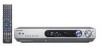
Let's play DVD video software CAUTION Make sure that the power cord plug is disconnected from the AC wall outlet before proceeding to speaker cord connections. If the conductor wires on the extremity of speaker cord are untwisted, there is a risk of short-circuiting. Be sure to twist them well before connecting the speaker cord. STEP 1 Connect the speakers, DVD and TV to the receiver. For details, see "Setting up the system" 8 ~ # Connection of speakers: COMPONENT VIDEO OUTPUT Y CB CR ANTENNA FM 75 Ω GND AM COMPONENT VIDEO INPUT (ASSIGNABLE) (VIDEO 2) DIGITAL IN (ASSIGNABLE) (DVD) COAX 2 (VIDEO 2) OPT 1 OPT 2 (VIDEO 1) (AUX) IN 2 IN 1 Y CB COAX 1 (DVD) DVD IN VIDEO 2 MONITOR IN OUT S VIDEO VIDEO IN VIDEO IN VIDEO OUT VIDEO IN MONITOR OUT CR R L L SUB WOOFER SURROUND BACK PRE OUT IN DVD PLAY IN REC OUT PLAY IN VIDEO 2 VIDEO 1 R IN AUX L CENTER R SURR L FRONT R SURR BACK/ SW SPEAKERS (6-8Ω) SW LR C RS LS BS Powered subwoofer LS Front Speakers L Center Speaker Surround Speakers C Surround Back Speaker R RECEIVER RS DVD SW BS ÷ If you want to connect two surround back speakers (LB and RB) to the PRE OUT SURROUND BACK jacks, see "PRE OUT jacks connections". $ Connection of DVD player: For the video input connection from the DVD player and the video output connection to the TV monitor, connect any one in a pair. Digital audio connection (Coaxial code) Component video connection S video connection Composite video connection Analog audio connection COMPONENT VIDEO OUTPUT Y CB CR ANTENNA FM 75 Ω GND AM COMPONENT VIDEO INPUT (ASSIGNABLE) (VIDEO 2) DIGITAL IN (ASSIGNABLE) (DVD) COAX 2 (VIDEO 2) OPT 1 OPT 2 (VIDEO 1) (AUX) IN 2 IN 1 Y CB COAX 1 (DVD) DVD IN VIDEO 2 MONITOR IN OUT S VIDEO VIDEO IN VIDEO IN VIDEO OUT VIDEO IN MONITOR OUT CR R L L SUB WOOFER SURROUND BACK PRE OUT IN DVD PLAY IN REC OUT PLAY IN VIDEO 2 VIDEO 1 R IN AUX L CENTER R SURR L FRONT R SURR BACK/ SW SPEAKERS (6-8Ω) 16 EN Connection of TV monitor: Component video connection S video connection Composite video connection COMPONENT VIDEO OUTPUT Y CB CR ANTENNA FM 75 Ω GND AM COMPONENT VIDEO INPUT (ASSIGNABLE) (VIDEO 2) DIGITAL IN (ASSIGNABLE) (DVD) COAX 2 (VIDEO 2) OPT 1 OPT 2 (VIDEO 1) (AUX) IN 2 IN 1 Y CB COAX 1 (DVD) DVD IN VIDEO 2 IN MONITOR OUT VIDEO IN VIDEO IN VIDEO OUT VIDEO IN MONITOR OUT S VIDEO R L CR L SUB WOOFER SURROUND BACK PRE OUT IN PLAY IN REC OUT PLAY IN DVD VIDEO 2 VIDEO 1 IN R AUX L CENTER R SURR L FRONT R SURR BACK/ SW SPEAKERS (6-8Ω) STEP 2 Set up the speakers. For details, see "Speaker settings" . * ~ ¡ ON/STANDBY SETUP INPUT SELECTOR MULTI CONTROL %/fi/@/#, ENTER 1 Connect the power cord to the AC wall outlet and press the ON/STANDBY key. 2 Press the SETUP key, press the MULTI CONTROL @ / # to select "SP SETUP" and press the ENTER. If you connect KENWOOD speaker system: 1 Press the MULTI CONTROL @ / # to select the model of the connected speaker system and press the ENTER. 1 "HTB1 6.1CH": Speaker system KS-4200EX*. 2 "HTB1 5.1CH": Speaker system KS-2200HT*. 3 "HTB2 6.1CH": Speaker system KS-3200HT*+KS-3200EX*, KS-5200EX*, KS-7200HT*+KS-3200EX*. 4 "HTB2 5.1CH": Speaker system KS-3200HT*, KS-5200HT*, KS-7200HT*. 5 "HTB3 6.1CH": Speaker system KS-8200EX*. 6 "HTB3 5.1CH": Speaker system KS-8200HT*. * Model availability may differ depending on the country and sales area. ÷ When the speaker setting is set to "HTB1 5.1CH", "HTB2 5.1CH" or "HTB3 5.1CH", the DOLBY PRO LOGIC IIx, DTS-ES and DOLBY DIGITAL EX listen modes cannot be selected. 2 If your selection is correct, press the MULTI CONTROL % / fi to select "OK" and press the ENTER. Now the speaker setup is complete. (Select "CANCEL" to return to the status before setup.) ÷ More detailed settings such as the volume level of each speaker and distance to each speaker are also available. ) ~ ¡ Continued to next page
-
 1
1 -
2
-
3
-
4
-
5
-
6
-
7
-
8
-
9
-
10
-
 11
11 -
 12
12 -
 13
13 -
 14
14 -
 15
15 -
 16
16 -
 17
17 -
 18
18 -
 19
19 -
 20
20 -
 21
21 -
22
-
23
-
24
-
25
-
26
-
27
-
28
-
29
-
30
-
31
-
32
-
33
-
34
-
35
-
36
-
37
-
38
-
39
-
40
-
41
-
42
-
43
-
44
-
45
-
46
-
47
-
48
-
49
-
50
-
51
-
52
-
53
-
54
-
55
-
56
-
57
-
58
-
59
-
60
 |
 |
