Kenwood XD-355 User Manual - Page 5
Names Of Controls And Indicators, Front Panel
 |
View all Kenwood XD-355 manuals
Add to My Manuals
Save this manual to your list of manuals |
Page 5 highlights
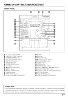
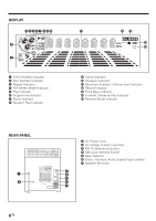
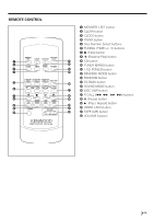
NAMES OF CONTROLS AND INDICATORS FRONT PANEL 1 EX.BASS / DEMO button 2 STANDBY / TIMER indicator 3 REVERSE MODE button 4 ON / STANDBY button 5 VIDEO / AUX button 6 TAPE (A/B) button 7 TUNER (BAND) button 8 CD button 9 2 (Reverse play) button 0 7 STOP button ! 3 (Play / repeat) button @ PHONES socket # PUSH OPEN (Tape A) $ (TAPE A) cassette compartment % Display ^ Disc tray & DISC SKIP button * 0 OPEN / CLOSE button ( SOUND MODE button ) CLOCK button ¡ TIMER button ™ MEMORY / SET button £ P. CALL (4 1 ¡ ¢) buttons ¢ VOLUME CONTROL knob ∞ TUNING / TIME (%UP fiDOWN) buttons § REC PAUSE button ¶ PUSH OPEN (Tape B) • (TAPE B) cassette compartment Standby mode While the standby indicator of the unit is lit, a small amount of current is flowing into the unit's internal circuitry to back up the memory. This condition is referred to as the standby mode of the unit. While the unit is in the standby mode, it can be turned ON from the remote control unit. 5 EN
-
 1
1 -
 2
2 -
 3
3 -
 4
4 -
 5
5 -
 6
6 -
 7
7 -
 8
8 -
 9
9 -
 10
10 -
 11
11 -
12
-
13
-
14
-
15
-
16
-
17
-
18
-
19
-
20
-
21
-
22
-
23
-
24
-
25
-
26
-
27
-
28
-
29
-
30
-
31
-
32
 |
 |
