Kyocera ECOSYS FS-1370DN FS-1370DN Operation Guide (Basic) - Page 26
Components at the Front of the Printer, USB Interface Connector
 |
View all Kyocera ECOSYS FS-1370DN manuals
Add to My Manuals
Save this manual to your list of manuals |
Page 26 highlights
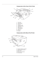
Components at the Front of the Printer 1 2 3 4 5 6 10 9 8 7 1 Top Cover 2 Paper Stopper 3 Top Tray 4 Operation Panel 5 USB Memory Slot 6 Right Cover 7 Paper Cassette 8 Front Cover 9 MP Tray 10 Subtray Components at the Rear of the Printer 11 12 13 14 15 11 Network Interface Connector 12 USB Interface Connector 13 Rear Cover 14 Power Cord Connector 15 Power Switch 1-2 Machine Parts
-
 1
1 -
2
-
3
-
4
-
5
-
6
-
7
-
8
-
9
-
10
-
11
-
12
-
13
-
14
-
15
-
16
-
17
-
18
-
19
-
20
-
 21
21 -
 22
22 -
 23
23 -
 24
24 -
 25
25 -
 26
26 -
 27
27 -
 28
28 -
 29
29 -
 30
30 -
 31
31 -
32
-
33
-
34
-
35
-
36
-
37
-
38
-
39
-
40
-
41
-
42
-
43
-
44
-
45
-
46
-
47
-
48
-
49
-
50
-
51
-
52
-
53
-
54
-
55
-
56
-
57
-
58
-
59
-
60
-
61
-
62
-
63
-
64
-
65
-
66
-
67
-
68
-
69
-
70
-
71
-
72
-
73
-
74
-
75
-
76
-
77
-
78
-
79
-
80
-
81
-
82
-
83
-
84
-
85
-
86
-
87
-
88
-
89
-
90
-
91
-
92
-
93
-
94
-
95
-
96
 |
 |

1-2
Machine Parts
Components at the Front of the Printer
1
Top Cover
2
Paper Stopper
3
Top Tray
4
Operation Panel
5
USB Memory Slot
6
Right Cover
7
Paper Cassette
8
Front Cover
9
MP Tray
10
Subtray
Components at the Rear of the Printer
11
Network Interface Connector
12
USB Interface Connector
13
Rear Cover
14
Power Cord Connector
15
Power Switch
1
2
3
4
6
7
8
9
10
5
11
14
12
15
13