Kyocera FS-C5200DN FS-C5100DN/C5200DN/C5300DN Operation Guide Rev-1.2 (BASIC) - Page 22
Components at the Front of the Printer, Main Charger Units on the Drum Units
 |
View all Kyocera FS-C5200DN manuals
Add to My Manuals
Save this manual to your list of manuals |
Page 22 highlights
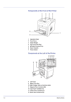
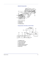
Components at the Front of the Printer 1 2 34 5 7 6 1 Operation Panel 2 Front Cover 3 Paper Stopper 4 Top Cover (Top Tray) 5 MP (Multi-Purpose) Tray 6 Paper Cassette 7 Power Switch Components at the Left of the Printer 11 12 13 14 8 10 9 8 Left Cover 9 Waste Toner Box 10 Main Charger Units on the Drum Units 11 Magenta Toner Container (M) 12 Cyan Toner Container (C) 13 Yellow Toner Container (Y) 14 Black Toner Container (K) 1-2 Machine Parts
-
 1
1 -
2
-
3
-
4
-
5
-
6
-
7
-
8
-
9
-
10
-
11
-
12
-
13
-
14
-
15
-
16
-
 17
17 -
 18
18 -
 19
19 -
 20
20 -
 21
21 -
 22
22 -
 23
23 -
 24
24 -
 25
25 -
 26
26 -
 27
27 -
28
-
29
-
30
-
31
-
32
-
33
-
34
-
35
-
36
-
37
-
38
-
39
-
40
-
41
-
42
-
43
-
44
-
45
-
46
-
47
-
48
-
49
-
50
-
51
-
52
-
53
-
54
-
55
-
56
-
57
-
58
-
59
-
60
-
61
-
62
-
63
-
64
-
65
-
66
-
67
-
68
-
69
-
70
-
71
-
72
-
73
-
74
-
75
-
76
-
77
-
78
-
79
-
80
 |
 |

1-2
Machine Parts
Components at the Front of the Printer
1
Operation Panel
2
Front Cover
3
Paper Stopper
4
Top Cover (Top Tray)
5
MP (Multi-Purpose) Tray
6
Paper Cassette
7
Power Switch
Components at the Left of the Printer
8
Left Cover
9
Waste Toner Box
10
Main Charger Units on the Drum Units
11
Magenta Toner Container (M)
12
Cyan Toner Container (C)
13
Yellow Toner Container (Y)
14
Black Toner Container (K)
2
5
6
1
3
7
4
8
9
10
11 12 13 14