Kyocera FS-C5200DN FS-C5100DN/C5200DN/C5300DN Operation Guide Rev-1.2 (BASIC) - Page 23
Internal Components, Components at the Rear of the Printer, Power Cord Connector
 |
View all Kyocera FS-C5200DN manuals
Add to My Manuals
Save this manual to your list of manuals |
Page 23 highlights
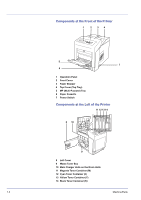
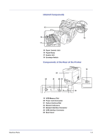
Machine Parts Internal Components 15 16 18 17 15 Paper Transfer Unit 16 Paper Ramp 17 Duplex Unit 18 Envelope Switch Components at the Rear of the Printer 19 25 20 21 22 23 24 19 USB Memory Slot 20 Power Cord Connector 21 Option Interface Slot 22 Network Indicators 23 Network Interface Connector 24 USB Interface Connector 25 Rear Cover 1-3
-
 1
1 -
2
-
3
-
4
-
5
-
6
-
7
-
8
-
9
-
10
-
11
-
12
-
13
-
14
-
15
-
16
-
17
-
 18
18 -
 19
19 -
 20
20 -
 21
21 -
 22
22 -
 23
23 -
 24
24 -
 25
25 -
 26
26 -
 27
27 -
 28
28 -
29
-
30
-
31
-
32
-
33
-
34
-
35
-
36
-
37
-
38
-
39
-
40
-
41
-
42
-
43
-
44
-
45
-
46
-
47
-
48
-
49
-
50
-
51
-
52
-
53
-
54
-
55
-
56
-
57
-
58
-
59
-
60
-
61
-
62
-
63
-
64
-
65
-
66
-
67
-
68
-
69
-
70
-
71
-
72
-
73
-
74
-
75
-
76
-
77
-
78
-
79
-
80
 |
 |

Machine Parts
1-3
Internal Components
15
Paper Transfer Unit
16
Paper Ramp
17
Duplex Unit
18
Envelope Switch
Components at the Rear of the Printer
19
USB Memory Slot
20
Power Cord Connector
21
Option Interface Slot
22
Network Indicators
23
Network Interface Connector
24
USB Interface Connector
25
Rear Cover
18
19
20
21
22
23
24
25
15
17
16