LG 50144803 User Guide - Page 13

LG 50144803 - DLE5955W 27in Electric Dryer Manual

Page 13 highlights

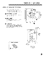
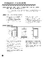
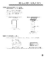
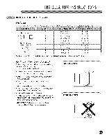
INSTALLATIONINSTRUCTIONS CHANGING THE DRYER VENT LOCATION Retaining Screw Your new dryer is shipped to vent to the rear. It can also be configured to vent to the bottom or side (right-side venting is not available on gas models). An adapter kit, part number 383EEL9001 B, may be purchased from your LG retailer. This kit contains the necessary duct components to change the dryer vent location. Rear Exhaust Duct I Remove the rear exhaust duct retaining screw. Pull out the exhaust duct. OPTION 1: Side Venting OPTION 2: Bottom f"_ Adapter Venting Duct Bracket Press the tabs on the knockout and carefully remove the knockout for the desired vent opening (right-side venting is not available on gas models). Press the adapter duct onto the blower housing and secure to the base of the dryer as shown. Press the adapter duct onto the blower housing and secure to the base of the dryer as shown. Cover Plate Cover Plate Elbow ,/ __J Elbow

  • 1
  • 2
  • 3
  • 4
  • 5
  • 6
  • 7
  • 8
  • 9
  • 10
  • 11
  • 12
  • 13
  • 14
  • 15
  • 16
  • 17
  • 18
  • 19
  • 20
  • 21
  • 22
  • 23
  • 24
  • 25
  • 26
  • 27
  • 28
  • 29
  • 30
  • 31
  • 32
  • 33
  • 34
  • 35
  • 36
  • 37
  • 38
  • 39
  • 40
  • 41
  • 42
  • 43
  • 44
  • 45
  • 46
  • 47
  • 48
  • 49
  • 50
  • 51
  • 52
  • 53
  • 54
  • 55
  • 56
  • 57
  • 58
  • 59
  • 60
  • 61
  • 62
  • 63
  • 64
  • 65
  • 66
  • 67
  • 68
  • 69
  • 70
  • 71
  • 72
  • 73
  • 74
  • 75
  • 76
  • 77
  • 78
  • 79
  • 80

INSTALLATIONINSTRUCTIONS
CHANGING
THE DRYER VENT LOCATION
Your new dryer
is shipped
to vent to the rear.
It can also be configured
to vent to the bottom
or side (right-side
venting
is not available
on
gas models).
An adapter
kit, part number
383EEL9001 B,
may be purchased
from
your LG retailer. This
kit contains
the necessary
duct
components
to
change
the dryer vent location.
Retaining
Screw
Rear
Exhaust
Duct
I
Remove the rear exhaust
duct
retaining
screw.
Pull out the exhaust
duct.
OPTION 1: Side
Venting
Press the tabs
on the knockout
and carefully
remove
the knockout
for the desired
vent
opening
(right-side
venting
is not available
on
gas models).
Press the adapter
duct
onto the
blower
housing
and secure to the base of the
dryer as shown.
Cover
Plate
Elbow
<38 om)
,/
Preassemble a 4-in. (10 cm) elbow to the next
4-in. (10 cm) duct section, and secure all joints
with duct tape.
Be sure that the male end of
the elbow faces AWAY from the dryer.
Insert the elbow/duct
assembly through the
side opening and press it onto the adapter
duct. Secure in place with duct tape.
Be sure that the male end of the duct
protrudes
1
V2
in. (3.8 cm) to connect the
remaining ductwork.
Attach cover plate to the back of the dryer with
included
screw.
OPTION 2: Bottom
Venting
f"_
Adapter
Duct
Bracket
Press the adapter
duct
onto the blower
housing
and secure
to the base of the dryer
as shown.
Cover
Plate
Elbow
__J
Insert the 4-in.
(10 cm) elbow through
the
rear opening
and press it onto the adapter
duct.
Be sure that the male end of the elbow
faces down
through
hole in the bottom
of the
dryer. Secure
in place
with duct
tape.
Attach
the cover
plate to the back of the
dryer with
included
screw.
15