LG LRBP1031W User Guide - Page 1
LG LRBP1031W - 10 Cu. Ft. Cabinet Depth Bottom Freezer Refrigerator Manual
 |
UPC - 048231777223
View all LG LRBP1031W manuals
Add to My Manuals
Save this manual to your list of manuals |
Page 1 highlights
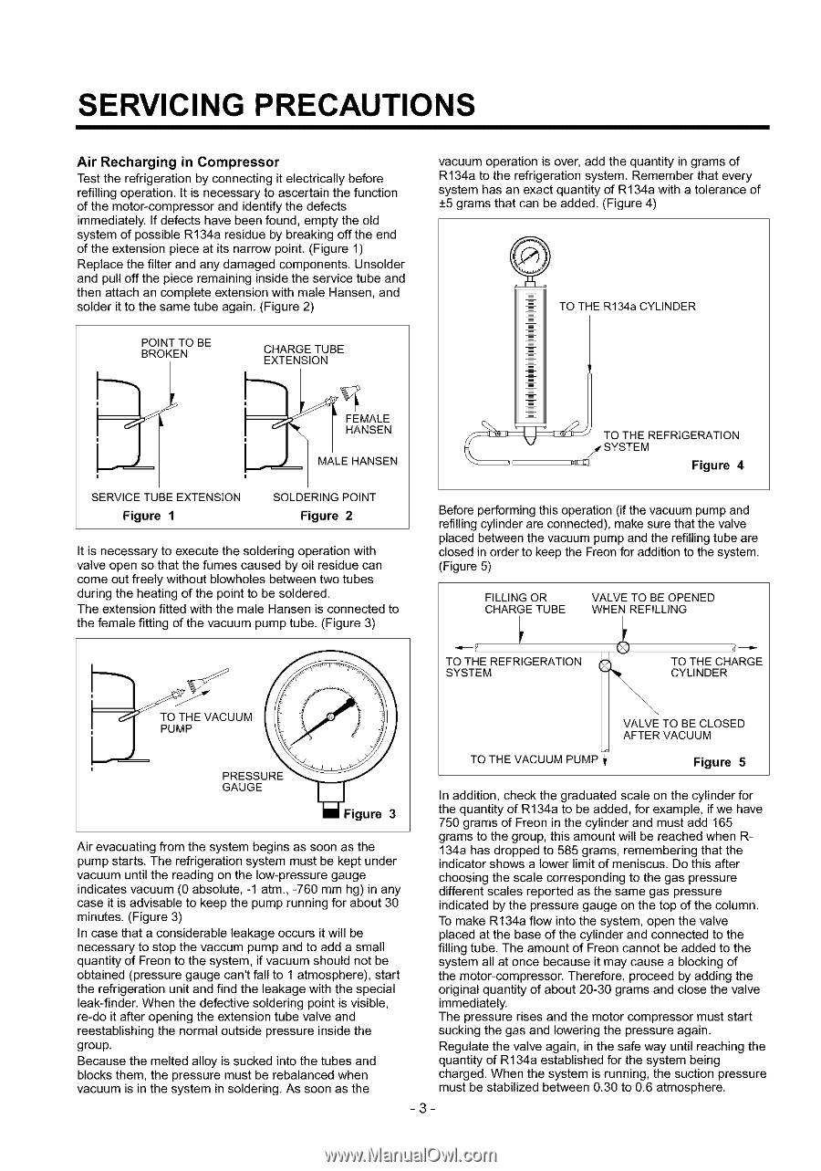
SERVICING PRECAUTIONS Air Recharging in Compressor Test the refrigeration by connecting it electrically before refilling operation. It is necessary to ascertain the function of the meter-compressor and identify the defects immediately. If defects have been found, empty the old system of possible R134a residue by breaking off the end of the extension piece at its narrow point. (Figure 1) Replace the filter and any damaged components. Unsolder and pull off the piece remaining inside the service tube and then attach an complete extension with male Hansen, and solder it to the same tube again. (Figure 2) POINT TO BE BROKEN CHARGE TUBE EXTENSION vacuum operation is over, add the quantity in grams of R134a to the refrigeration system. Remember that every system has an exact quantity of R134a with a tolerance of +5 grams that can be added. (Figure 4) q\ i TO TiE R134a CYLINDER MALE HANSEN SERVICE TUBE EXTENSION Figure 1 SOLDERING POINT Figure 2 It is necessary to execute the soldering operation with valve open so that the fumes caused by oil residue can come out freely without blowholes between two tubes during the heating of the point to be soldered. The extension fitted with the male Hansen is connected to the female fitting of the vacuum pump tube. (Figure 3) '__ TOsTTHEEMFRRiGEF_lr_ N4 Before performing this operation (if the vacuum pump and refilling cylinder are connected), make sure that the valve placed between the vacuum pump and the refilling tube are closed in order to keep the Freon for addition to the system. (Figure 5) FILLING OR CHARGE TUBE VALVE TO BE OPENED WHEN REFILLING TO THE REFRIGERATION SYSTEM TO THE CHARGE CYLINDER VALVE TO BE CLOSED UM AFTER VACUUM PRESSURE GAUGE TO THE VACUUM PUMP Figure 5 In addition, check the graduated scale on the cylinder for igure 3 Air evacuating from the system begins as soon as the pump starts. The refrigeration system must be kept under vacuum until the reading on the low-pressure gauge indicates vacuum (0 absolute, -1 atm., -760 mm hg) in any case it is advisable to keep the pump running for about 30 minutes. (Figure 3) In case that a considerable leakage occurs it will be necessary to stop the vaccum pump and to add a small quantity of Freon to the system, if vacuum should not be obtained (pressure gauge can't fall to 1 atmosphere), start the refrigeration unit and find the leakage with the special leak-finder. When the defective soldering point is visible, the quantity of R134a to be added, for example, if we have 750 grams of Freon in the cylinder and must add 165 grams to the group, this amount will be reached when R134a has dropped to 585 grams, remembering that the indicator shows a lower limit of meniscus. De this after choosing the scale corresponding to the gas pressure different scales reported as the same gas pressure indicated by the pressure gauge on the top of the column. To make R134a flow into the system, open the valve placed at the base of the cylinder and connected to the filling tube. The amount of Freon cannot be added to the system all at once because it may cause a blocking of the motor-compressor. Therefore, proceed by adding the original quantity of about 20-30 grams and close the valve immediately. re-do it after opening the extension tube valve and The pressure rises and the motor compressor must start reestablishing the normal outside pressure inside the sucking the gas and lowering the pressure again. group. Regulate the valve again, in the safe way until reaching the Because the melted alloy is sucked into the tubes and blocks them, the pressure must be rebalanced when vacuum is in the system in soldering. As soon as the quantity of R134a established for the system being charged. When the system is running, the suction pressure must be stabilized between 0.30 to 0.6 atmosphere. -3-
-
 1
1 -
 2
2 -
 3
3 -
 4
4 -
 5
5 -
 6
6 -
 7
7 -
8
-
9
-
10
-
11
-
12
-
13
-
14
-
15
-
16
-
17
-
18
-
19
-
20
-
21
-
22
-
23
-
24
-
25
-
26
-
27
-
28
-
29
-
30
-
31
-
32
-
33
 |
 |