LG LRBP1031W User Guide - Page 19
Function, Electric, Circuits, Circuit, Reset Circuit
 |
UPC - 048231777223
View all LG LRBP1031W manuals
Add to My Manuals
Save this manual to your list of manuals |
Page 19 highlights
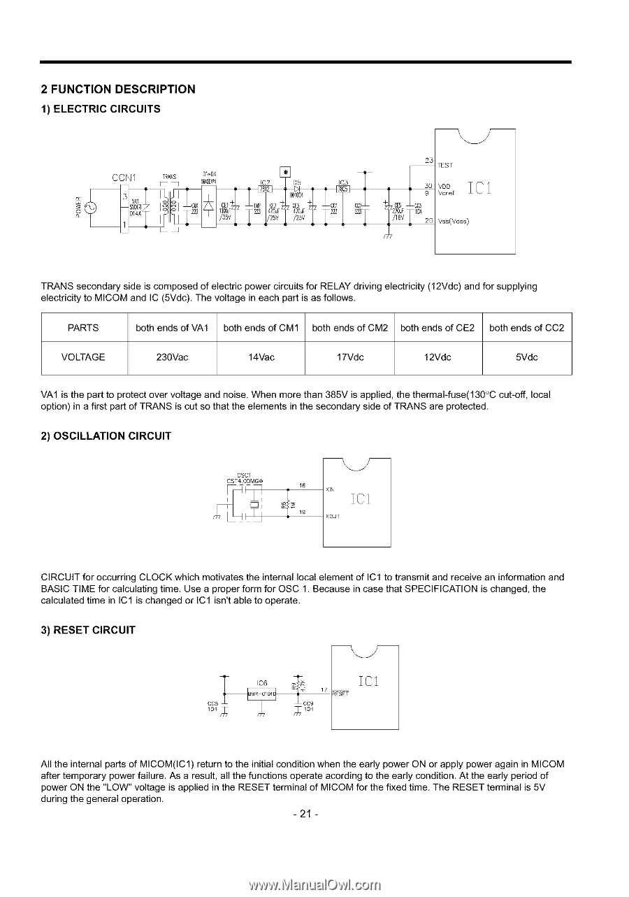
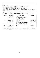
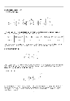
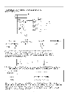
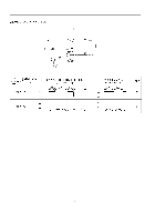
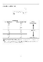
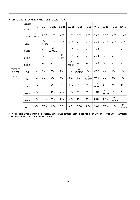
2 FUNCTION DESCRIPTION 1) ELECTRIC CIRCUITS 23 TEST Vss(Vass) TRANS secondary side is composed of electric power circuits for RELAY driving electricity (12Vdc) and for supplying electricity to MICOM and IC (5Vdc). The voltage in each part is as follows. PARTS both ends of VA1 both ends of CM1 both ends of CM2 both ends of CE2 both ends of CC2 VOLTAGE 230Vac 14Vac 17Vdc 12Vdc 5Vdc VA1 is the part to protect over voltage and noise, When more than 385V is applied, the thermaFfuse(130°C cut-off, local option) in a first part of TRANS is cut so that the elements in the secondary side of TRANS are protected. 2) OSCILLATION CIRCUIT osc1 CST4 00MGW r[-, oT CIRCUIT for occurring CLOCK which motivates the internal local element of IC1 to transmit and receive an information and BASIC TIME for calculating time. Use a proper form for OSC 1, Because in case that SPECIFICATION is changed, the calculated time in IC1 is changed or IC1 isn't able to operate. 3) RESET CIRCUIT _ESET All the internal parts of MICOM(IC1) return to the initial condition when the early power ON or apply power again in MICOM after temporary power failure. As a result, all the functions operate acording to the early condition. At the early period of power ON the "LOW" voltage is applied in the RESET terminal of MICOM for the fixed time. The RESET terminal is 5V during the general operation. -21 -
-
 1
1 -
2
-
3
-
4
-
5
-
6
-
7
-
8
-
9
-
10
-
11
-
12
-
13
-
 14
14 -
 15
15 -
 16
16 -
 17
17 -
 18
18 -
 19
19 -
 20
20 -
 21
21 -
 22
22 -
 23
23 -
 24
24 -
25
-
26
-
27
-
28
-
29
-
30
-
31
-
32
-
33
 |
 |