LG LRBP1031W User Guide - Page 8
Circuit, Diagram - specifications
 |
UPC - 048231777223
View all LG LRBP1031W manuals
Add to My Manuals
Save this manual to your list of manuals |
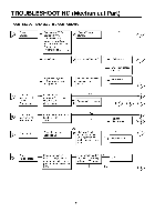
Page 8 highlights
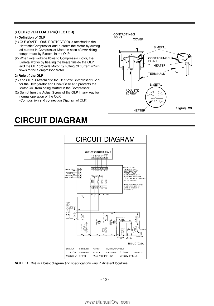
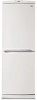
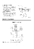
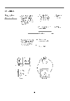
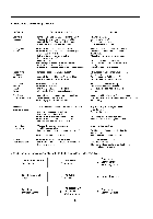
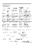
30LP (OVER LOAD PROTECTOR) 1) Definition of OLP (1) OLP (OVER LOAD PROTECTOR) is attached to the Hermetic Compressor and protects the Motor by cutting off current in Compressor Motor in case of over-rising temperature by Bimetal in the OLP. (2) When over-voltage flows to Compressor motor, the Bimetal works by heating the heater inside the OLP, and the OLP protects Motor by cutting off current which flows to the Compressor Motor. 2) Role of the OLP (1) The OLP is attached to the Hermetic Compressor used for the Refrigerator and Show Case and prevents the Motor Coil from being started in the Compressor. (2) De not turn the Adjust Screw of the OLP in any way for normal operation of the OLP. (Composition and connection Diagram of OLP) CIRCUIT DIAGRAM CONTACTINGD POINT COVER BIMETAL ADJUSTB SCREW BIMETAL HEATER Figure 20 CIRCUIT DIAGRAM 3854JD1026A BK:BLACK BN:BROWN YL:YELLOW GN:GREEN SB:SKY BLUE PK:PINK RD;RED BO BRIGHTORANGE BL:BLUE PR;PURPLE GY:GRAY WH:WHITE GN/YL:GREENHELLOW WH/BK;WHITEtBLACK NOTE : 1. This is a basic diagram and specifications vary in different localities. -10-
-
 1
1 -
2
-
 3
3 -
 4
4 -
 5
5 -
 6
6 -
 7
7 -
 8
8 -
 9
9 -
 10
10 -
 11
11 -
 12
12 -
 13
13 -
14
-
15
-
16
-
17
-
18
-
19
-
20
-
21
-
22
-
23
-
24
-
25
-
26
-
27
-
28
-
29
-
30
-
31
-
32
-
33
 |
 |