LG MU-42PM12X Service Manual
LG MU-42PM12X Manual
 |
View all LG MU-42PM12X manuals
Add to My Manuals
Save this manual to your list of manuals |
LG MU-42PM12X manual content summary:
- LG MU-42PM12X | Service Manual - Page 1
CANADA : http//biz.lgservice.com USA : http//www.lgservice.com : http//lgservice.com/techsup.html PLASMA MONITOR SERVICE MANUAL CHASSIS : RF-043E MODEL : MU-42PM11 MU-42PM12X CAUTION BEFORE SERVICING THE CHASSIS, READ THE SAFETY PRECAUTIONS IN THIS MANUAL. - LG MU-42PM12X | Service Manual - Page 2
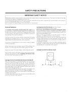
chassis have special safety-related characteristics. These parts are identified by in the Schematic Diagram and Replacement Parts List. It is essential that these special safety parts should be replaced with the same components as recommended in this manual to prevent X-RADIATION, Shock, Fire, or - LG MU-42PM12X | Service Manual - Page 3
TABLE OF CONTENTS DESCRIPTION OF CONTROLS 4 SPECIFICATIONS 7 ADJUSTMENT INSTRUCTIONS 8 TROUBLE SHOOTING GUIDE 13 BLOCK DIAGRAM 24 EXPLODED VIEW 26 EXPLODED VIEW PARTS LIST 27 REPLACEMENT PARTS LIST 28 SCHEMATIC DIAGRAM PRINTED CIRCUIT BOARD -3- - LG MU-42PM12X | Service Manual - Page 4
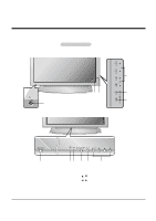
may be somewhat different from your monitor. MU-42/50PM10/11 series ON/OFF 1 MU-42/50PM20 series 6 5 32 4 ON/OFF 1 23 1. Main Power Button 2. Remote Control Sensor 3. Power Standby Indicator Illuminates red in standby mode. Illuminates green when the Monitor is turned on. 4. INPUT SELECT - LG MU-42PM12X | Service Manual - Page 5
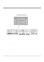
to these jacks. 8. EXTERNAL SPEAKER (8 ohm output) Connect to optional external speaker(s). * For further information, refer to 'Speaker & Speaker Stand' manual. 9. POWER CORD SOCKET This Monitor operates on an AC power. The voltage is indicated on the Specifications page. Never attempt to operate - LG MU-42PM12X | Service Manual - Page 6
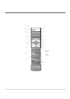
Functions - When using the remote control, aim it at the remote control sensor on the monitor. - Under certain conditions such as if the remote IR signal is interrupted, the remote control may not function. Press the key again as necessary. POWER Switches the Monitor between ON and STANDBY. SLEEP - LG MU-42PM12X | Service Manual - Page 7
SPECIFICATIONS MODELS MU-42PM11/20 MU-42PM12X MU-50PM10/11/20 Width (inches / mm) Height (inches / mm) Depth (inches / mm) Weight (pounds / kg) Resolution Power requirement Color Operating Temperature Range Operating Humidity Range 42 / 1066 25.8 / 656 3.8 / 97.5 64.6 / 29.3 49.3 / 1253 29.3 / - LG MU-42PM12X | Service Manual - Page 8
instructions apply to the RF-043E Chassis. 2. Specification adjustment. O Enter into HEAT-RUN MODE 1) Press the POWER ON KEY on Service R/C. 2) OSD display and screen display 100% full WHITE black level part of the screen. 4. HDCP Download 4-1. Setting Up the LGIDS (1) Click on 'setup' to install - LG MU-42PM12X | Service Manual - Page 9
ADJUSTMENT INSTRUCTIONS (1) Click on 'Key Generation (G)'. (2) Input the number of Confirmation it's possible within HDCP\CreatedKeyFile) 4-3. HDCP Download Method (1) Input power of Stand-By 5V. (Download must be executed only when it is on Stand-by) (2) The RS-232C(9PIN) must be connected to the - LG MU-42PM12X | Service Manual - Page 10
ADJUSTMENT INSTRUCTIONS Each PCB assembly must be checked by Check JIG Set before assembly. (Take special note of the Power PCB, which can easily damage the PDP module) 5. POWER PCB Assy Voltage Adjustments (Va, Vs Voltage Adjustments) 5-1. Test Equipment : D.M.M. 1EA 3) Turn RV501, to adjust the - LG MU-42PM12X | Service Manual - Page 11
to PDP module surface when you adjust. O Manual adjustment is also possible by the following sequence. (1) Select white pattern of heat-run mode by pressing power key on the Service Remote Control (S R/C) then allow to heat run at least 15 minutes. (2) Supply Window Pattern signal to DVI input using - LG MU-42PM12X | Service Manual - Page 12
ADJUSTMENT INSTRUCTIONS 9. Auto RGB Color Balance 9-1. Required Test Equipment Pattern Equipment: PC Pattern Generator (VG828, VG854, 801GF, MSP3240A) (16 Gray Scale Pattern output(RGB output Level: 0.7Vp-p) 9-2. - LG MU-42PM12X | Service Manual - Page 13
TROUBLE SHOOTING GUIDE 1. Power Board 1-1. General Power Flow Start check Doesn't the Yes screen whole come out? It is identical No with Power Off condition? Yes No 1. Check the Power St-by 5V signal circuit. Yes 4. Check the 5V Monitor signal circuit. Yes 5. Check the VSC RL-ON signal. - LG MU-42PM12X | Service Manual - Page 14
TROUBLE SHOOTING GUIDE 1-2. 3510V00182A Power Board Structure 1 2 3 T502: Vs Trans T702: Va Trans T101: St-by Trans T103: Low Voltage Trans - 14 - - LG MU-42PM12X | Service Manual - Page 15
TROUBLE SHOOTING GUIDE 1-3. 3501V00180A Power Board Structure 1 2 3 T221: Vs Trans T271: Va Trans T121: St-by Trans T201: Low Voltage Trans - 15 - - LG MU-42PM12X | Service Manual - Page 16
TROUBLE SHOOTING GUIDE 2. No Power (1) Symptom ¯ No indication of Power. ¯ No front LED. (2) Check follow No Power cord connected? Yes Cable connecting the Line Filter No and Power Switch connected? Yes Is the Power Switch connected to No Power Board? Yes Is Fuse(F101) on Power Board No - LG MU-42PM12X | Service Manual - Page 17
TROUBLE SHOOTING GUIDE 3. Protect Mode (1) Symptom ¯ Will not fully turn on ¯ The Relay "clicks" ¯ Front LED changes from Green to Red (2) Check follow Is the Power Board No good? Yes Are all connectors No connected? Yes No Is the Y-Board good? Yes No Is the Z-Board good? Yes No Is the X-Board - LG MU-42PM12X | Service Manual - Page 18
No COF of X, Y, Z? Is output the normality Low/High voltage except Stand-by 5V? No Replace Power Board. After connecting each connector well, No is operation good? Replace connector. Check Fuse(F52) on Y-B/D? (In case of open, replace fuse) Is the output voltage Yes good after removing Yes P5 - LG MU-42PM12X | Service Manual - Page 19
TROUBLE SHOOTING GUIDE 5. Abnormal Display 5-1. No OSD (1) Symptom ¯ LED is green ¯ No OnScreen Display (2) Check follow Check the LVDS No cable? Is the LVDS cable Yes connected well? No Reset cable. Yes Replace cable. Is the VSC Digital No Operates the Thine Yes Board good? IC(IC1100)? - LG MU-42PM12X | Service Manual - Page 20
TROUBLE SHOOTING GUIDE 5-2. In case of does't display the screen into specific mode (1) Symptom ¯ The screen does not become the display from specific input mode (AV, Component, RGB, DVI). (2) Check follow ¯ Check the all input mode should become normality display. ¯ Check the Video(Main)/Data(Sub), - LG MU-42PM12X | Service Manual - Page 21
TROUBLE SHOOTING GUIDE (4) Abnormal display in Component 480i mode Is the Video Decoder No Are the Input No Is Scaler good? Are the Input voltage, IIC Comm. and HV sync good? No Replace IC Replace IC Replace IC (5) Abnormal display in Component DTV mode(480p, 720p, 1080i) Is normal the No - LG MU-42PM12X | Service Manual - Page 22
TROUBLE SHOOTING GUIDE (6) Abnormal display in RGB DTV mode Is normal the No Are Yes No Is normal the Scaler? Are the Input voltage, IIC Comm. and HV sync good? No Replace IC Replace IC Replace IC (7) Abnormal display in RGB PC mode Is normal the No Are the Input voltage, IIC No M52758 - LG MU-42PM12X | Service Manual - Page 23
TROUBLE SHOOTING GUIDE 6. No sound (1) Symptom ¯ LED is green ¯ Screen display but no audio (2) Check follow Check Speaker No cable? Yes Is the SPK cable connected well? Yes Replace SPK cable No Reset cable. Audio normal on No RGB/DVI? Yes Is the Flat cable Yes connected well? No - LG MU-42PM12X | Service Manual - Page 24
BLOCK DIAGRAM - 24 - - LG MU-42PM12X | Service Manual - Page 25
NOTES - 25 - - LG MU-42PM12X | Service Manual - Page 26
EXPLODED VIEW(MU-42PM11) 300 305 560 310 301 303 200 207 206 202 102 101 203 205 201 540 204 210 590 530 580 541 501 520 103 104 400 - 26 - - LG MU-42PM12X | Service Manual - Page 27
,SUB TUNER RF043E MU-42PM11 ANALOG B/D MANUAL 540 6871VSMABFA PCB ASSEMBLY,SUB PSW RF043A MAILBU 541 5020V01009A BUTTON,POWER MZ-42PM10 ABS, AF-303S 1KEY NON 560 6871VSMG62A PCB ASSEMBLY,SUB CONT RF043E MU-42PM10 LOCAL KEY ASSY 580 3501V00182B BOARD ASSEMBLY,POWER RT-42PX12X RF043B - LG MU-42PM12X | Service Manual - Page 28
EXPLODED VIEW(MU-42PM12X) 300 305 301 303 560 310 501 101 102 103 101 202 206 201 540 590 530 541 204 203 200 207 205 580 210 520 400 - 28 - - LG MU-42PM12X | Service Manual - Page 29
MANUAL 530 6871VSMACBB PCB ASSEMBLY,SUB A/V RF043E MU-42PM10X SUB ANALOG MANAUL 540 6871VSMABFA PCB ASSEMBLY,SUB PSW RF043A MAILBU 541 5020V01009A BUTTON,POWER MZ-42PM10 ABS, AF-303S 1KEY NON 560 6871VSMG62A PCB ASSEMBLY,SUB CONT RF043E MU-42PM10 LOCAL KEY ASSY 580 3501V00182B BOARD - LG MU-42PM12X | Service Manual - Page 30
REPLACEMENT PARTS LIST For Capacitor & Resistors, the charactors at 2nd and 3rd digit in the P/No. means as follows; CC, CX, CK, CN : Ceramic CQ : Polyestor CE : Electrolytic RD : Carbon Film RS : Metal Oxide Film RN : Metal Film RF : Fusible LOCA. NO PART NO DESCRIPTION IC IC100 IC1000 - LG MU-42PM12X | Service Manual - Page 31
REPLACEMENT PARTS LIST LOCA. NO PART NO DESCRIPTION Q302 Q305 Q306 Q307 Q308 Q309 Q310 Q319 KDS226 SOT-23 CHIP KDS226 SOT-23 CHIP KDS226 SOT-23 CHIP KDS226 SOT-23 LOCA. NO PART NO DESCRIPTION D1301 D1302 D1303 D1304 D1305 D1306 D131 D1501 D1503 D400 D5001 LD001 LD1000 LD1001 LD1002 LD1003 - LG MU-42PM12X | Service Manual - Page 32
REPLACEMENT PARTS LIST LOCA. NO PART NO DESCRIPTION C1074 C1077 C1108 C1128 C1129 C1145 C1146 16V 20% 100UF MVG 16V M 47UF MVG 16V M 47UF MVG 16V M 47UF MVG 16V M LOCA. NO PART NO DESCRIPTION C1391 C1400 C1402 C1404 C1410 C1415 C1425 C222 C223 C224 C230 C251 C254 C258 C261 C263 C272 C274 - LG MU-42PM12X | Service Manual - Page 33
REPLACEMENT PARTS LIST LOCA. NO PART NO DESCRIPTION C637 C651 C671 C672 C673 C674 C703 470UF MV 16V 20% 470UF MV 16V 20% 100UF MVG 16V M 100UF MVG 16V M LOCA. NO PART NO DESCRIPTION C9014 0CE107SF6DC 100UF MVG 16V M JACK JK200 JK201 JK202 JK203 P101 P102 P200 P201 SP1 6612JH003CA - LG MU-42PM12X | Service Manual - Page 34
REPLACEMENT PARTS LIST LOCA. NO PART NO DESCRIPTION AR612 AR613 AR614 AR615 AR616 AR617 AR618 AR701 AR707 AR708 L1333 L1500 L200 L202 L203 L204 L205 L205 L206 L207 L208 PART NO 6210VC0006A 6210VC0006A 6210VC0006A 6210VC0006A 6210VC0006A 6210VC0006A 6210VC0006A 6210VC0006A 6200JB8010L 6200JB8010L - LG MU-42PM12X | Service Manual - Page 35
REPLACEMENT PARTS LIST LOCA. NO PART NO DESCRIPTION L209 L210 L211 L212 L213 L214 ACCESSORIES A1 3828VA0520B MANUAL,OWNERS RF043E LOCA. NO PART NO " 3828VA0520C A2 6710V00136H A3 6410VUH005A A4 6850J00004A DESCRIPTION MANUAL,OWNERS *LGECI REMOTE CONTROLLER POWER CORD,PS204 125V/ - LG MU-42PM12X | Service Manual - Page 36
P/NO : 3828VD0206B Nov., 2004 Printed in Korea CANADA: LG Electronics Canada, Inc. 550 Matheson Boulevard East Mississauga, Ontario L4Z 4G3 USA : LG Electronics Alabama, Inc. P.O.Box 240007, 201 James Record Road Bldg 3 Huntsville, AL 35824 - LG MU-42PM12X | Service Manual - Page 37
- LG MU-42PM12X | Service Manual - Page 38
- LG MU-42PM12X | Service Manual - Page 39
- LG MU-42PM12X | Service Manual - Page 40
- LG MU-42PM12X | Service Manual - Page 41
- LG MU-42PM12X | Service Manual - Page 42
MAIN(TOP) MAIN(BOTTOM) TUNER(TOP) TUNER(BOTTOM) CONTROL(TOP) CONTROL(BOTTOM) POWER S/W(TOP) POWER S/W(BOTTOM)
-
 1
1 -
 2
2 -
 3
3 -
 4
4 -
 5
5 -
 6
6 -
 7
7 -
8
-
9
-
10
-
11
-
12
-
13
-
14
-
15
-
16
-
17
-
18
-
19
-
20
-
21
-
22
-
23
-
24
-
25
-
26
-
27
-
28
-
29
-
30
-
31
-
32
-
33
-
34
-
35
-
36
-
37
-
38
-
39
-
40
-
41
-
42
 |
 |

PLASMA MONITOR
SERVICE MANUAL
CAUTION
BEFORE SERVICING THE CHASSIS,
READ THE SAFETY PRECAUTIONS IN THIS MANUAL.
CHASSIS : RF-043E
MODEL : MU-42PM11
MU-42PM12X
CANADA : http//biz.lgservice.com
USA
: http//www.lgservice.com
: http//lgservice.com/techsup.html