LG MU-42PM12X Service Manual - Page 17
Protect Mode - left side
 |
View all LG MU-42PM12X manuals
Add to My Manuals
Save this manual to your list of manuals |
Page 17 highlights
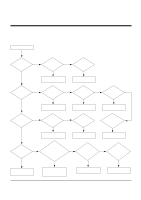
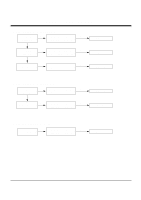
TROUBLE SHOOTING GUIDE 3. Protect Mode (1) Symptom ¯ Will not fully turn on ¯ The Relay "clicks" ¯ Front LED changes from Green to Red (2) Check follow Is the Power Board No good? Yes Are all connectors No connected? Yes No Is the Y-Board good? Yes No Is the Z-Board good? Yes No Is the X-Board good? Yes Is the Ctrl Board No good? Yes Is the VSC Board No good? Yes Is normal the No COF of X, Y, Z? Is output the normality Low/High voltage except Stand-by 5V? No Replace Power Board. After connecting each connector well, No is operation good? Replace connector. Check Fuse(F52) on Y-B/D? (In case of open, replace fuse) Is the output voltage Yes good after removing Yes P5, P6 connector of Y-B/D? Replace Y-Board. Check Fuse(FS1, FS2) on Z-B/D? (In case of open, replace fuse) Is the output voltage Yes good after removing Yes P1 connector of ZB/D? Replace Z-Board. Is the output voltage good after Yes removing P1, 2, 3, 4, 6, 7 connector of X-B/D? If after removing P1, P2, P3, P4 the output voltage is normal: Replace Right X-B/D. If after removing P6, P7 the output voltage is normal: Replace Left X-B/D. Is the output voltage good after Yes removing P1, 2, 101, 300, 701, 702 connector of Ctrl-B/D? Replace X-Board. Is the output voltage good after removing P1000, P1200? If after removing P1000 the output is Yes normal: Replace Analog Board If after removing P1200 the output is normal: Replace Digital Board After crisis COF of each board, check the normality operates. If in case normality operates, correspondence COF Fail is replace the module. - 17 -
-
 1
1 -
2
-
3
-
4
-
5
-
6
-
7
-
8
-
9
-
10
-
11
-
 12
12 -
 13
13 -
 14
14 -
 15
15 -
 16
16 -
 17
17 -
 18
18 -
 19
19 -
 20
20 -
 21
21 -
 22
22 -
23
-
24
-
25
-
26
-
27
-
28
-
29
-
30
-
31
-
32
-
33
-
34
-
35
-
36
-
37
-
38
-
39
-
40
-
41
-
42
 |
 |
