LG MU-42PM12X Service Manual - Page 11
Adjustment of White Balance, Auto Component Color Balance - power supply
 |
View all LG MU-42PM12X manuals
Add to My Manuals
Save this manual to your list of manuals |
Page 11 highlights
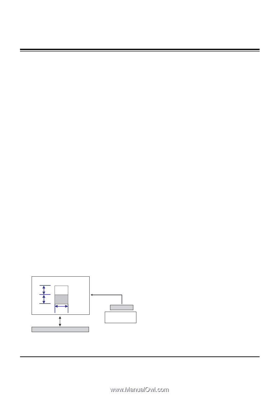
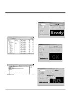
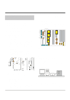
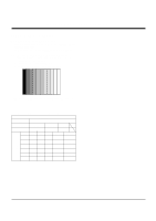
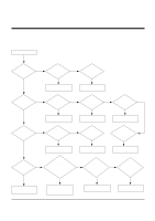
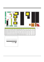
ADJUSTMENT INSTRUCTIONS 6-4. Sequence of Adjustment (1) DDC Data Input for Analog-RGB 1) Put the set on the table and turn the power on. 2) Connect PC Serial to D-sub 15P Cable of jig for DDC adjustment to RGB terminal (D-Sub 15Pin). 3) Operate S/W for DDC record and select DDC data for Analog RGB in Model Menu. 4) Operate EDID Write command. 5) Operate EDID Read command and check whether Check Sum is as below. MU-42PM11: CB MU-42PM12X/MU-50PM10: DC 6) If Check Sum is not CB(or DC), repeat 3) ~ 4). 7) If Check Sum is CB(or DC), DDC data for Analog-RGB input is completed. (2) DDC Data input for Digital-RGB(DVI) 1) Connect PC Serial to DVI Cable of jig for DDC adjustment to DVI terminal (DVI Jack). 2) Operate S/W for DDC record and select DDC data for digital RGB in model menu. 3) Operate EDID Write command. 4) Operate EDID Read command and check whether Check sum is as below. MU-42PM11: 4A MU-42PM12X/MU-50PM10: CD 5) If Check sum is not 4A(or CD), repeat 3) ~ 4). 6) If Check sum is 4A(or CD), DDC data for Analog-RGB input is completed. 7. Adjustment of White Balance 7-1. Required Equipment Color Analyzer (CA-100 or similar product) 7-2. Connection Diagram of Equipment for Measuring 1/4 H 1/4 H High 160 gray Low 80 gray 1/4 W RS-232C Serial Communication COLOR ANALYZER TYPE; CA-100 DVI Signal Input XGA 60Hz Signal Window MSPG-2100 or MSTG-5200 7-3. Adjustment of White Balance O Operate the Zero-calibration of the CA-100, then stick sensor to PDP module surface when you adjust. O Manual adjustment is also possible by the following sequence. (1) Select white pattern of heat-run mode by pressing power key on the Service Remote Control (S R/C) then allow to heat run at least 15 minutes. (2) Supply Window Pattern signal to DVI input using Pattern Generator. 1) Input Signal: XGA 60Hz 2) Input the Window Pattern(Horizontal 25%, Vertical 50%(Top High 25% + Bottom Low 25%)) (Refer to Fig. 11) (3) Press the FRONT-AV KEY on R/C for converting input DVI mode. (4) Press ADJ key twice on S R/C. (White Balance) (5) High Adjustment Stick sensor to center of 160 Gray Level(High Window Pattern), select Red Gain and Green Gain using D, E key on S R/C. Press VOL +, - keys to adjust until color coordination matches below. X; 0.285±0.003, Y; 0.285±0.003 (6) Low Adjustment Stick sensor to center of 80 Gray Level(Low Window Pattern), select Red Offset and Green Offset using D, E key on S R/C. Press VOL +, - keys to adjust until color coordination matches below. X; 0.285±0.006, Y; 0.285±0.006 (7) Repeat above step (5) and (6) for the best condition of High and Low. (8) Exit adjustment mode using A Key. 8. Auto Component Color Balance 8-1. Required Test Equipment Pattern Equipment: MSP3240A or similar product (16 Gray Scale Pattern output(Component output Level: 0.7Vp-p) 8-2. Method of Auto RGB Color Balance (1) Input RGB Source : Component 720p 16 Gray Scale Pattern At this time, input the Y, Pb and Pr signal. (2) Press ADJ KEY on the S R/C. (3) Press Vol. + KEY and operate To set. (4) Auto-RGB OK means completed adjustment. (Fig. 11) White Balance Adjustment - 11 -
-
 1
1 -
2
-
3
-
4
-
5
-
 6
6 -
 7
7 -
 8
8 -
 9
9 -
 10
10 -
 11
11 -
 12
12 -
 13
13 -
 14
14 -
 15
15 -
 16
16 -
17
-
18
-
19
-
20
-
21
-
22
-
23
-
24
-
25
-
26
-
27
-
28
-
29
-
30
-
31
-
32
-
33
-
34
-
35
-
36
-
37
-
38
-
39
-
40
-
41
-
42
 |
 |