Lantronix SLC 8 Lantronix SLC - User Guide - Page 123
Data Settings, ISDN Settings, GSM/GPRS Settings, Static Routes
 |
View all Lantronix SLC 8 manuals
Add to My Manuals
Save this manual to your list of manuals |
Page 123 highlights
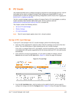
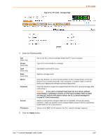
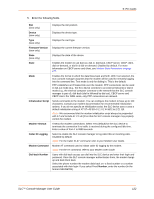
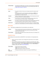
9: PC Cards Dial-back Delay For dial-back and CBCP Server, the number of seconds between the dial-in and dial-out portions of the dialing sequence. For more information about CBCP, see Modem State Parameters on page 277. Data Settings Baud Data Bits Parity Stop Bits Flow Control The speed with which the device port exchanges data with the attached serial device. From the drop-down list, select the baud rate. Most devices use 9600 for the administration port, so this is the default. Check the equipment settings and documentation for the proper baud rate. Number of data bits used to transmit a character. From the drop-down list, select the number of data bits. The default is 8 data bits. Parity checking is a rudimentary method of detecting simple, single-bit errors. From the drop-down list, select the parity. The default is none. The number of stop bit(s) used to indicate that a byte of data has been transmitted. From the drop-down list, select the number of stop bits. The default is 1. A method of preventing buffer overflow and loss of data. The available methods include none, xon/xoff (software), and RTS/CTS (hardware). The default is none. ISDN Settings Note: These fields are disabled if the PC Card inserted is not an ISDN card. Channel Phone Number Select to indicate which B channel on the ISDN card to use. Valid values are 1 and 2. (The B-channel is the channel that carries the main data.) Only one 64K channel can be used at a time. Phone number associated with the B channel. May have up to 20 characters. Any format is acceptable. GSM/GPRS Settings These settings are only active when a GSM/GPRS PC card modem is in the appropriate slot. Notes: Please consult your wireless carrier configuration requirements for more detailed information. Dial-out GPRS connections may replace the default route and DNS entries. Static routes may be required to maintain access to subnets that are not directly attached to the SLC console manager. Click the Static Routes link (above Data Settings) to configure a static route. (See Routing on page 58.) Dial-out Mode PIN Retype PIN Select the type of dial-out connection: GPRS: (General Packet Radio Service) GSM: (Global System for Mobile communication) PIN (personal identification number) for accessing the GSM/GPRS card. SLC™ Console Manager User Guide 123
-
 1
1 -
2
-
3
-
4
-
5
-
6
-
7
-
8
-
9
-
10
-
11
-
12
-
13
-
14
-
15
-
16
-
17
-
18
-
19
-
20
-
21
-
22
-
23
-
24
-
25
-
26
-
27
-
28
-
29
-
30
-
31
-
32
-
33
-
34
-
35
-
36
-
37
-
38
-
39
-
40
-
41
-
42
-
43
-
44
-
45
-
46
-
47
-
48
-
49
-
50
-
51
-
52
-
53
-
54
-
55
-
56
-
57
-
58
-
59
-
60
-
61
-
62
-
63
-
64
-
65
-
66
-
67
-
68
-
69
-
70
-
71
-
72
-
73
-
74
-
75
-
76
-
77
-
78
-
79
-
80
-
81
-
82
-
83
-
84
-
85
-
86
-
87
-
88
-
89
-
90
-
91
-
92
-
93
-
94
-
95
-
96
-
97
-
98
-
99
-
100
-
101
-
102
-
103
-
104
-
105
-
106
-
107
-
108
-
109
-
110
-
111
-
112
-
113
-
114
-
115
-
116
-
117
-
 118
118 -
 119
119 -
 120
120 -
 121
121 -
 122
122 -
 123
123 -
 124
124 -
 125
125 -
 126
126 -
 127
127 -
 128
128 -
129
-
130
-
131
-
132
-
133
-
134
-
135
-
136
-
137
-
138
-
139
-
140
-
141
-
142
-
143
-
144
-
145
-
146
-
147
-
148
-
149
-
150
-
151
-
152
-
153
-
154
-
155
-
156
-
157
-
158
-
159
-
160
-
161
-
162
-
163
-
164
-
165
-
166
-
167
-
168
-
169
-
170
-
171
-
172
-
173
-
174
-
175
-
176
-
177
-
178
-
179
-
180
-
181
-
182
-
183
-
184
-
185
-
186
-
187
-
188
-
189
-
190
-
191
-
192
-
193
-
194
-
195
-
196
-
197
-
198
-
199
-
200
-
201
-
202
-
203
-
204
-
205
-
206
-
207
-
208
-
209
-
210
-
211
-
212
-
213
-
214
-
215
-
216
-
217
-
218
-
219
-
220
-
221
-
222
-
223
-
224
-
225
-
226
-
227
-
228
-
229
-
230
-
231
-
232
-
233
-
234
-
235
-
236
-
237
-
238
-
239
-
240
-
241
-
242
-
243
-
244
-
245
-
246
-
247
-
248
-
249
-
250
-
251
-
252
-
253
-
254
-
255
-
256
-
257
-
258
-
259
-
260
-
261
-
262
-
263
-
264
-
265
-
266
-
267
-
268
-
269
-
270
-
271
-
272
-
273
-
274
-
275
-
276
-
277
-
278
-
279
-
280
-
281
-
282
-
283
-
284
-
285
-
286
-
287
-
288
-
289
-
290
-
291
-
292
-
293
-
294
-
295
-
296
-
297
-
298
-
299
 |
 |
