Lenovo B470e Lenovo B470/B470e Hardware Maintenance Manual - Page 55
Keyboard, Removal steps of PCI Express Mini Card for wireless LAN/WAN, When installing
 |
View all Lenovo B470e manuals
Add to My Manuals
Save this manual to your list of manuals |
Page 55 highlights
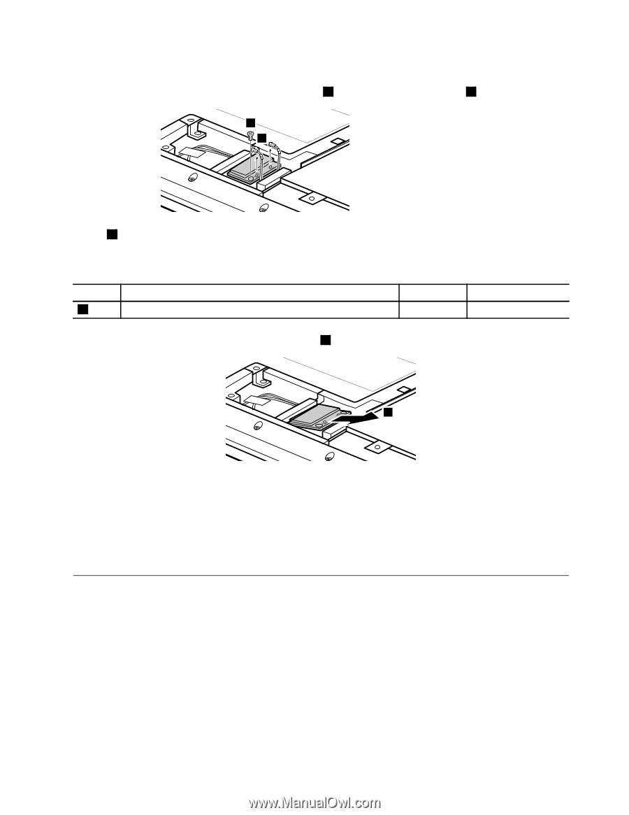
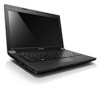
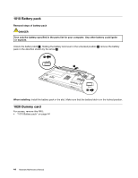
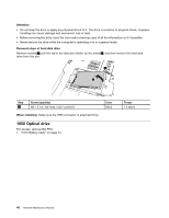
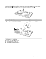
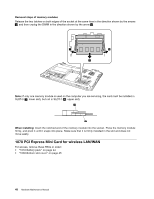
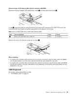
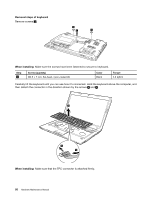
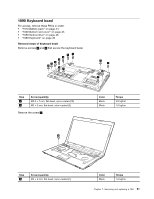
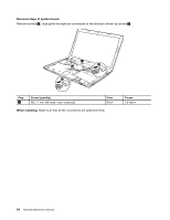
Removal steps of PCI Express Mini Card for wireless LAN/WAN Disconnect the two wireless LAN cables (black, white) 1 , and then remove the screw 2 . 2 1 In step 1 , unplug the jacks by using the removal tool antenna RF connector (P/N: 08K7159) or pick the connectors with your fingers and gently unplug them in the direction of the arrow. Note: Some models might have a third white antenna cable. Step 2 Screw (quantity) M2 × 3 mm, flat-head, nylon-coated (1) Color Black Torque 1.6 kgfcm Remove the card in the direction shown by the arrow 3 . 3 When installing: • In models with a wireless LAN card that has two antenna connectors, plug the black cable (1st) (MAIN) into the jack labeled 1, and the white cable (2nd) (AUX) into jack labeled 2 on the card. • In models with a wireless LAN card that has three antenna connectors, plug the black cable (1st) (MAIN) into the jack labeled 1, the grey cable (3rd) into jack labeled 3, and the white cable (2nd) (AUX) into jack labeled 2 on the card. 1080 Keyboard For access, remove these FRUs in order: • "1010 Battery pack" on page 44 Chapter 7. Removing and replacing a FRU 49
-
 1
1 -
2
-
3
-
4
-
5
-
6
-
7
-
8
-
9
-
10
-
11
-
12
-
13
-
14
-
15
-
16
-
17
-
18
-
19
-
20
-
21
-
22
-
23
-
24
-
25
-
26
-
27
-
28
-
29
-
30
-
31
-
32
-
33
-
34
-
35
-
36
-
37
-
38
-
39
-
40
-
41
-
42
-
43
-
44
-
45
-
46
-
47
-
48
-
49
-
 50
50 -
 51
51 -
 52
52 -
 53
53 -
 54
54 -
 55
55 -
 56
56 -
 57
57 -
 58
58 -
 59
59 -
 60
60 -
61
-
62
-
63
-
64
-
65
-
66
-
67
-
68
-
69
-
70
-
71
-
72
-
73
-
74
-
75
-
76
-
77
-
78
-
79
-
80
-
81
-
82
-
83
-
84
-
85
-
86
-
87
-
88
-
89
-
90
-
91
-
92
 |
 |