Lenovo B470e Lenovo B470/B470e Hardware Maintenance Manual - Page 56
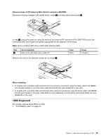
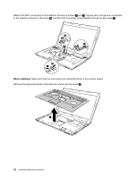
Removal steps of keyboard, When installing, Make sure that the FPC connector is attached firmly.
 |
View all Lenovo B470e manuals
Add to My Manuals
Save this manual to your list of manuals |
Page 56 highlights
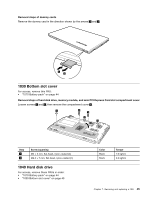
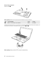
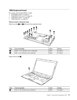
Removal steps of keyboard Remove screws 1 . 1 1 1 When installing: Make sure the screws have been fastened to secure to keyboard. Step 1 Screw (quantity) M2.5 × 7 mm, flat-head, nylon-coated (3) Color Black Torque 3.0 kgfcm Carefully lift the keyboard until you can see how it's connected. Hold the keyboard above the computer, and then detach the connector in the direction shown by the arrows 4 and 5 . 3 4 5 When installing: Make sure that the FPC connector is attached firmly. 50 Hardware Maintenance Manual
-
 1
1 -
2
-
3
-
4
-
5
-
6
-
7
-
8
-
9
-
10
-
11
-
12
-
13
-
14
-
15
-
16
-
17
-
18
-
19
-
20
-
21
-
22
-
23
-
24
-
25
-
26
-
27
-
28
-
29
-
30
-
31
-
32
-
33
-
34
-
35
-
36
-
37
-
38
-
39
-
40
-
41
-
42
-
43
-
44
-
45
-
46
-
47
-
48
-
49
-
50
-
 51
51 -
 52
52 -
 53
53 -
 54
54 -
 55
55 -
 56
56 -
 57
57 -
 58
58 -
 59
59 -
 60
60 -
 61
61 -
62
-
63
-
64
-
65
-
66
-
67
-
68
-
69
-
70
-
71
-
72
-
73
-
74
-
75
-
76
-
77
-
78
-
79
-
80
-
81
-
82
-
83
-
84
-
85
-
86
-
87
-
88
-
89
-
90
-
91
-
92
 |
 |
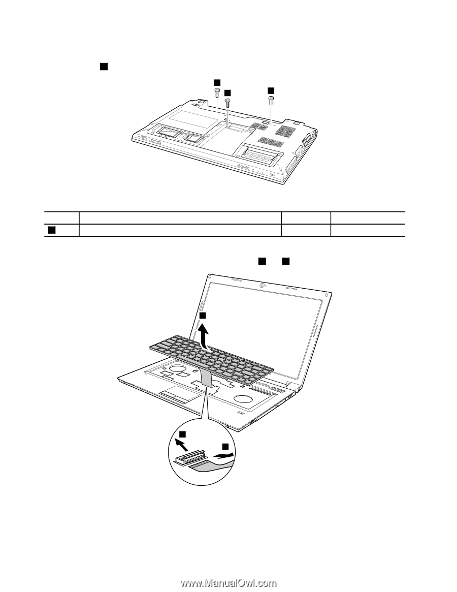
Removal steps of keyboard
Remove screws
1
.
1
1
1
When installing:
Make sure the screws have been fastened to secure to keyboard.
Step
Screw (quantity)
Color
Torque
1
M2.5 × 7 mm, flat-head, nylon-coated (3)
Black
3.0 kgfcm
Carefully lift the keyboard until you can see how it’s connected. Hold the keyboard above the computer, and
then detach the connector in the direction shown by the arrows
4
and
5
.
3
4
5
When installing:
Make sure that the FPC connector is attached firmly.
50
Hardware Maintenance Manual