Lenovo B470e Lenovo B470/B470e Hardware Maintenance Manual - Page 58
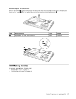
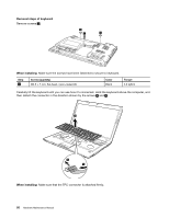
Make sure that the connectors are attached firmly to the system board.
 |
View all Lenovo B470e manuals
Add to My Manuals
Save this manual to your list of manuals |
Page 58 highlights
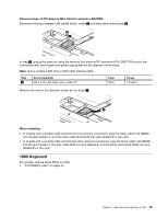
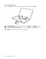
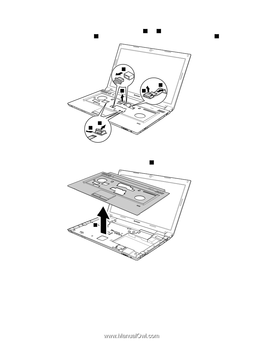
Detach the FPC connectors in the direction shown by arrows 4 and 5 . Unplug two microphone connectors in the direction shown by the arrow 6 , and the LCD connector in the direction shown by the arrow 7 . 6 5 7 4 4 5 When installing: Make sure that the connectors are attached firmly to the system board. Remove the keyboard bezel in the direction shown by the arrow 8 . 8 52 Hardware Maintenance Manual
-
 1
1 -
2
-
3
-
4
-
5
-
6
-
7
-
8
-
9
-
10
-
11
-
12
-
13
-
14
-
15
-
16
-
17
-
18
-
19
-
20
-
21
-
22
-
23
-
24
-
25
-
26
-
27
-
28
-
29
-
30
-
31
-
32
-
33
-
34
-
35
-
36
-
37
-
38
-
39
-
40
-
41
-
42
-
43
-
44
-
45
-
46
-
47
-
48
-
49
-
50
-
51
-
52
-
 53
53 -
 54
54 -
 55
55 -
 56
56 -
 57
57 -
 58
58 -
 59
59 -
 60
60 -
 61
61 -
 62
62 -
 63
63 -
64
-
65
-
66
-
67
-
68
-
69
-
70
-
71
-
72
-
73
-
74
-
75
-
76
-
77
-
78
-
79
-
80
-
81
-
82
-
83
-
84
-
85
-
86
-
87
-
88
-
89
-
90
-
91
-
92
 |
 |
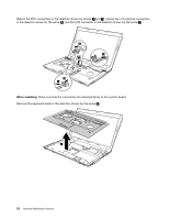
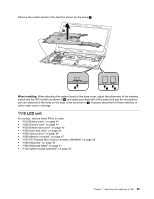
Detach the FPC connectors in the direction shown by arrows
4
and
5
. Unplug two microphone connectors
in the direction shown by the arrow
6
, and the LCD connector in the direction shown by the arrow
7
.
6
7
5
4
5
4
When installing:
Make sure that the connectors are attached firmly to the system board.
Remove the keyboard bezel in the direction shown by the arrow
8
.
8
52
Hardware Maintenance Manual