Lenovo C320 Lenovo C225\C320\C325 Hardware Maintenance Manual - Page 54
Step 18. Secure the new motherboard to the chassis using the screws.
 |
View all Lenovo C320 manuals
Add to My Manuals
Save this manual to your list of manuals |
Page 54 highlights
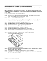
For models C220 refer to the below illustration. (7 screws) For models C225 and C325 refer to the below illustration. (7 screws) For models C320 refer to the below illustration. (9 screws) Step 17. Place the new motherboard into the chassis, aligning the screw holes in the motherboard with the mounting holes in the chassis. Step 18. Secure the new motherboard to the chassis using the screws. Step 19. Attach all related components to the new motherboard. 50 Lenovo C2/C3 Hardware Maintenance Manual
-
 1
1 -
2
-
3
-
4
-
5
-
6
-
7
-
8
-
9
-
10
-
11
-
12
-
13
-
14
-
15
-
16
-
17
-
18
-
19
-
20
-
21
-
22
-
23
-
24
-
25
-
26
-
27
-
28
-
29
-
30
-
31
-
32
-
33
-
34
-
35
-
36
-
37
-
38
-
39
-
40
-
41
-
42
-
43
-
44
-
45
-
46
-
47
-
48
-
 49
49 -
 50
50 -
 51
51 -
 52
52 -
 53
53 -
 54
54 -
 55
55 -
 56
56 -
 57
57 -
 58
58 -
 59
59 -
60
-
61
 |
 |
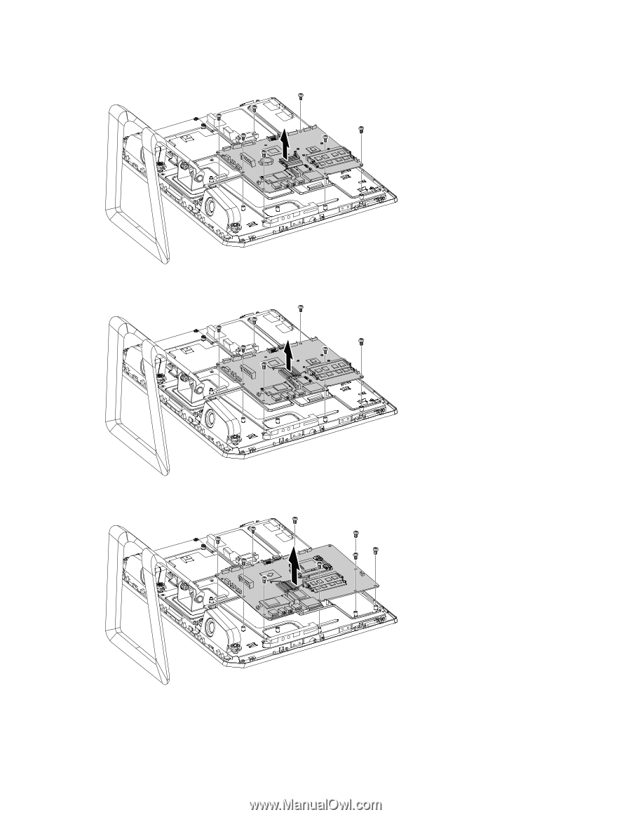
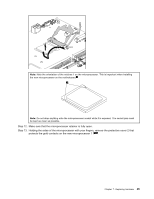
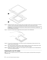
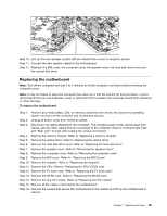
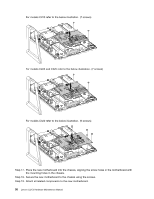
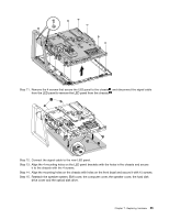
For models C220 refer to the below illustration. (7 screws)
For models C225 and C325 refer to the below illustration. (7 screws)
For models C320 refer to the below illustration. (9 screws)
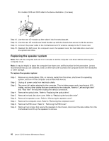
Step 17. Place the new motherboard into the chassis, aligning the screw holes in the motherboard with
the mounting holes in the chassis.
Step 18. Secure the new motherboard to the chassis using the screws.
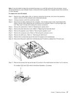
Step 19. Attach all related components to the new motherboard.
50
Lenovo C2/C3 Hardware Maintenance Manual