Lenovo C320 Lenovo C225\C320\C325 Hardware Maintenance Manual - Page 59
Step 14. Align the mounting holes on the chassis with holes on the front bezel and secure it with 15 screws.
 |
View all Lenovo C320 manuals
Add to My Manuals
Save this manual to your list of manuals |
Page 59 highlights
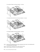
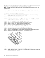
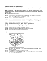
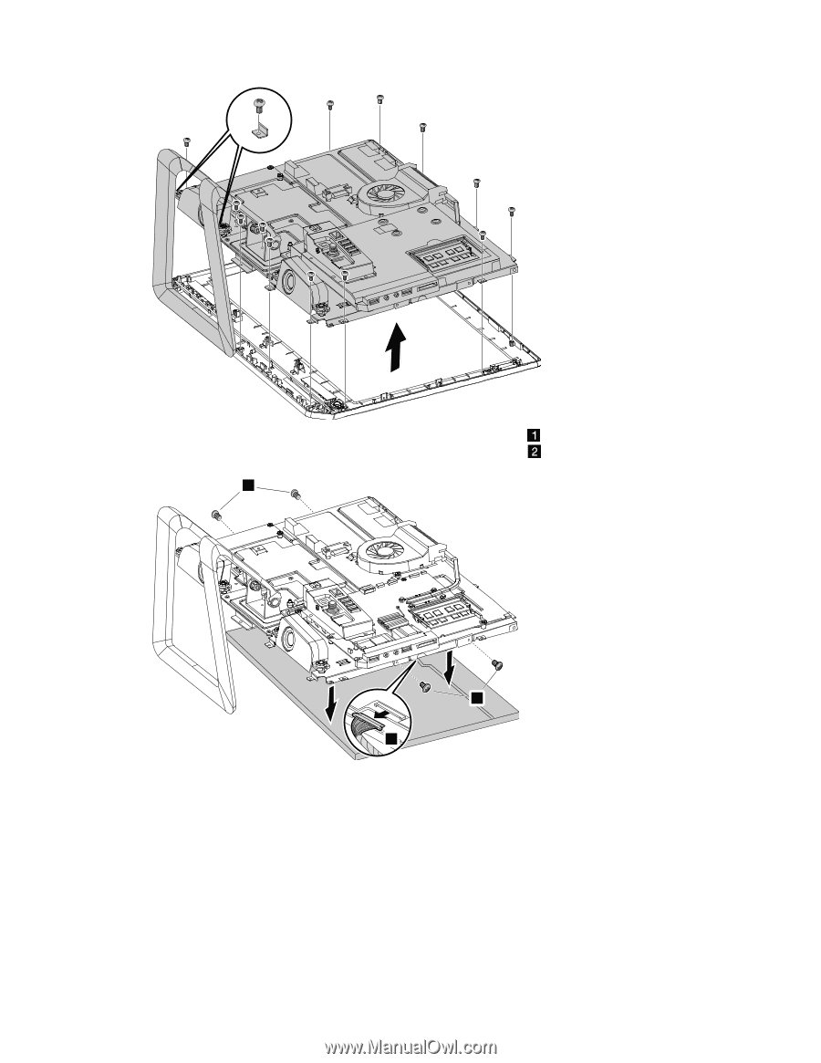
Step 11. Remove the 4 screws that secure the LED panel to the chassis and disconnect the signal cable from the LED panel to remove the LED panel from the chassis. 1 1 2 Step 12. Connect the signal cable to the new LED panel. Step 13. Align the 4 mounting holes on the LED panel brackets with the holes in the chassis and secure it to the chassis with the 4 screws. Step 14. Align the mounting holes on the chassis with holes on the front bezel and secure it with 15 screws. Step 15. Reattach the speaker system, EMI cover, the computer cover, the speaker cover, the hard disk drive cover and the optical disk drive. Chapter 7. Replacing hardware 55
-
 1
1 -
2
-
3
-
4
-
5
-
6
-
7
-
8
-
9
-
10
-
11
-
12
-
13
-
14
-
15
-
16
-
17
-
18
-
19
-
20
-
21
-
22
-
23
-
24
-
25
-
26
-
27
-
28
-
29
-
30
-
31
-
32
-
33
-
34
-
35
-
36
-
37
-
38
-
39
-
40
-
41
-
42
-
43
-
44
-
45
-
46
-
47
-
48
-
49
-
50
-
51
-
52
-
53
-
 54
54 -
 55
55 -
 56
56 -
 57
57 -
 58
58 -
 59
59 -
 60
60 -
 61
61
 |
 |
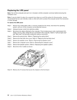
Step 11. Remove the 4 screws that secure the LED panel to the chassis
and disconnect the signal cable
from the LED panel to remove the LED panel from the chassis.
2
1
1
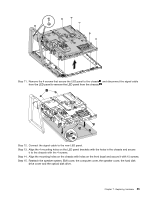
Step 12. Connect the signal cable to the new LED panel.
Step 13. Align the 4 mounting holes on the LED panel brackets with the holes in the chassis and secure
it to the chassis with the 4 screws.
Step 14. Align the mounting holes on the chassis with holes on the front bezel and secure it with 15 screws.
Step 15. Reattach the speaker system, EMI cover, the computer cover, the speaker cover, the hard disk
drive cover and the optical disk drive.
Chapter 7
.
Replacing hardware
55