Lenovo Edge 15 Laptop Hardware Maintenance Manual - Lenovo Flex 2 Pro-15, Leno - Page 52
Removal steps of system board continued, head, nylok
 |
View all Lenovo Edge 15 Laptop manuals
Add to My Manuals
Save this manual to your list of manuals |
Page 52 highlights
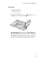
Lenovo Flex 2 Pro-15/Edge 15 Hardware Maintenance Manual Figure 10. Removal steps of system board (continued) Remove two screws f and remove the system board by arrow 7. 6 6 7 Step Screw (quantity) Color Torque f M 2.0 × 4.0 mm, flat‐head, nylok‐coated (2) Silver 1.85±0.15kgfcm When installing: When attaching the system board to the base cover, adjust the placement of USB, HDMI and RJ‐45 ports to make sure that they are attached to the holes on the base cover properly. Improper placement of the ports may cause damage. 48
-
 1
1 -
2
-
3
-
4
-
5
-
6
-
7
-
8
-
9
-
10
-
11
-
12
-
13
-
14
-
15
-
16
-
17
-
18
-
19
-
20
-
21
-
22
-
23
-
24
-
25
-
26
-
27
-
28
-
29
-
30
-
31
-
32
-
33
-
34
-
35
-
36
-
37
-
38
-
39
-
40
-
41
-
42
-
43
-
44
-
45
-
46
-
 47
47 -
 48
48 -
 49
49 -
 50
50 -
 51
51 -
 52
52 -
 53
53 -
 54
54 -
 55
55 -
 56
56 -
 57
57 -
58
-
59
-
60
-
61
-
62
-
63
-
64
-
65
-
66
-
67
-
68
-
69
-
70
-
71
-
72
-
73
-
74
-
75
-
76
-
77
-
78
-
79
 |
 |

Lenovo Flex 2 Pro-15/Edge 15 Hardware Maintenance Manual
48
Figure 10. Removal steps of system board (continued)
Remove two screws
and remove the system board by arrow
.
When installing:
When attaching the system board to the base cover, adjust the
placement of USB, HDMI and RJ
‐
45 ports to make sure that they are attached to
the holes on the base cover properly. Improper placement of the ports may cause
damage.
Step
Screw (quantity)
Color
Torque
M 2.0 × 4.0 mm, flat
‐
head, nylok
‐
coated (2)
Silver
1.85±0.15kgfcm
f
7
6
7
6
f