Lenovo Erazer X510 Lenovo Erazer X510 Hardware Maintenance Manual - Page 27
Locating connectors, controls and components - overclock
 |
View all Lenovo Erazer X510 manuals
Add to My Manuals
Save this manual to your list of manuals |
Page 27 highlights
Chapter 7. Locating connectors, controls and components This section provides illustrations to help locate the various connectors, controls and components of the computer. Front view of the chassis 7 8 9 10 11 12 13 1 2 3456 1. LED light Off/On button 8. Power button (LED color is always white) 2. Memory card readers 9. Side air vents with LED light inside (LED color is always blue) 3. USB 3.0 connector 10. Optical drive 4. Headphone connector 11. Expansion 5.25" ODD bay 5. Microphone connector 12. Hot-swappable hard disk frame 6. USB 3.0 connector / USB power off charging connector 13. Front LED light 7. Overclock button © Copyright Lenovo 2013, 2013 21
-
 1
1 -
2
-
3
-
4
-
5
-
6
-
7
-
8
-
9
-
10
-
11
-
12
-
13
-
14
-
15
-
16
-
17
-
18
-
19
-
20
-
21
-
 22
22 -
 23
23 -
 24
24 -
 25
25 -
 26
26 -
 27
27 -
 28
28 -
 29
29 -
 30
30 -
 31
31 -
 32
32 -
33
-
34
-
35
-
36
-
37
-
38
-
39
-
40
-
41
-
42
-
43
-
44
-
45
-
46
-
47
-
48
-
49
-
50
-
51
-
52
-
53
-
54
-
55
-
56
-
57
-
58
-
59
 |
 |

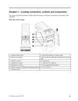
Chapter 7.
Locating connectors, controls and components
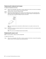
This section provides illustrations to help locate the various connectors, controls and components of the
computer.
Front view of the chassis
1. LED light Off/On button
8. Power button (LED color is always white)
2. Memory card readers
9. Side air vents with LED light inside (LED color is always
blue)
3. USB 3.0 connector
10. Optical drive
4. Headphone connector
11. Expansion 5.25" ODD bay
5. Microphone connector
12. Hot-swappable hard disk frame
6. USB 3.0 connector / USB power off charging connector
13. Front LED light
7. Overclock button
© Copyright Lenovo 2013, 2013
21