Lenovo Erazer X510 Lenovo Erazer X510 Hardware Maintenance Manual - Page 52
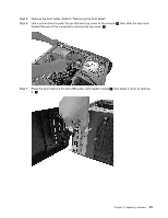
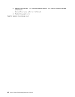
Line up the new power board with the bracket, then secure the power board with the two pins.
 |
View all Lenovo Erazer X510 manuals
Add to My Manuals
Save this manual to your list of manuals |
Page 52 highlights
Step 7. Push the four pins to release power board cover as shown. Step 8. Push the two pins to release the power board from top cover. 1 Step 9. Slide the power board out as shown. 2 Step 10. Install the new power board: a. Line up the new power board with the bracket, then secure the power board with the two pins. b. Connect the power board cable to the connector on the power board. c. Reattach the top cover. 46 Lenovo Erazer X510Hardware Maintenance Manual
-
 1
1 -
2
-
3
-
4
-
5
-
6
-
7
-
8
-
9
-
10
-
11
-
12
-
13
-
14
-
15
-
16
-
17
-
18
-
19
-
20
-
21
-
22
-
23
-
24
-
25
-
26
-
27
-
28
-
29
-
30
-
31
-
32
-
33
-
34
-
35
-
36
-
37
-
38
-
39
-
40
-
41
-
42
-
43
-
44
-
45
-
46
-
 47
47 -
 48
48 -
 49
49 -
 50
50 -
 51
51 -
 52
52 -
 53
53 -
 54
54 -
 55
55 -
 56
56 -
 57
57 -
58
-
59
 |
 |

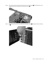
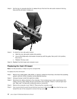
Step 7.
Push the four pins to release power board cover as shown.
Step 8.
Push the two pins to release the power board from top cover.
1
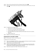
Step 9.
Slide the power board out as shown.
2
Step 10. Install the new power board:
a.
Line up the new power board with the bracket, then secure the power board with the two pins.
b.
Connect the power board cable to the connector on the power board.
c.
Reattach the top cover.
46
Lenovo Erazer X510Hardware Maintenance Manual