Lenovo Erazer X510 Lenovo Erazer X510 Hardware Maintenance Manual - Page 45
Replacing the Wi-Fi card
 |
View all Lenovo Erazer X510 manuals
Add to My Manuals
Save this manual to your list of manuals |
Page 45 highlights
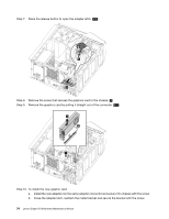
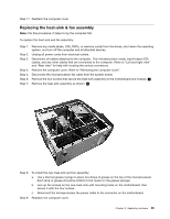
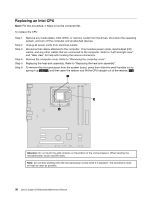
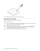
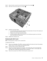
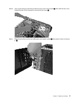
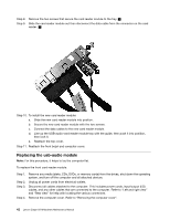
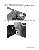
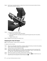
Step 5. Remove the four screws that secure the Power supply to the chassis. 1 Step 6. Slide then lift the Power supply out of chassis. 2 Step 7. Install the new power supply: a. Line up the holes on the new power supply with mounting holes on the rear of the chassis and secure it to the chassis with the four screws. b. Reattach the power supply supporting bracket. c. Connect the power cables to the connectors on the motherboard, graphic card, hard disk drive, solid state drive, optical drive. Step 8. Reattach the computer cover. Replacing the Wi-Fi card Note: For this procedure, it helps to lay the computer flat. To replace the Wi-Fi card: Step 1. Step 2. Step 3. Step 4. Remove any media (disks, CDs, DVDs, or memory cards) from the drives, shut down the operating system, and turn off the computer and all attached devices. Unplug all power cords from electrical outlets. Disconnect all cables attached to the computer. This includes power cords, input/output (I/O) cables, and any other cables that are connected to the computer. Refer to "Left and right view" and "Rear view" for help with locating the various connectors. Remove the computer cover. Refer to "Removing the computer cover". Chapter 8. Replacing hardware 39
-
 1
1 -
2
-
3
-
4
-
5
-
6
-
7
-
8
-
9
-
10
-
11
-
12
-
13
-
14
-
15
-
16
-
17
-
18
-
19
-
20
-
21
-
22
-
23
-
24
-
25
-
26
-
27
-
28
-
29
-
30
-
31
-
32
-
33
-
34
-
35
-
36
-
37
-
38
-
39
-
 40
40 -
 41
41 -
 42
42 -
 43
43 -
 44
44 -
 45
45 -
 46
46 -
 47
47 -
 48
48 -
 49
49 -
 50
50 -
51
-
52
-
53
-
54
-
55
-
56
-
57
-
58
-
59
 |
 |
