Lenovo G555 Lenovo G555 Hardware Maintenance Manual V2.0 - Page 45
Fan assembly and Heat Sink assembly - system board
 |
View all Lenovo G555 manuals
Add to My Manuals
Save this manual to your list of manuals |
Page 45 highlights
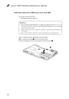
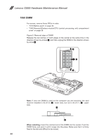
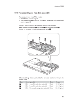
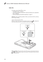
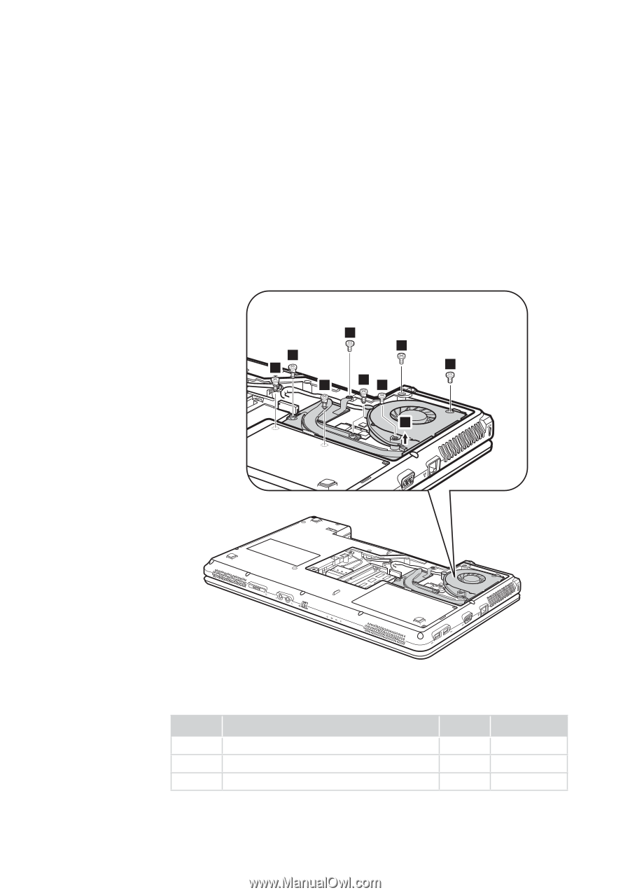
Lenovo G555 1070 Fan assembly and Heat Sink assembly For access, remove these FRUs in order: •• "1010 Battery pack" on page 34 •• "1040 Memory/Wireless module/CPU (central processing unit) compartment cover" on page 38 Figure 7. Removal steps of fan assembly and heat sink assembly Note: Remove three screws 1, one screw 2 and four spring screws 3. Unplug the connector in the direction shown by arrow 4. 2 3 3 1 1 3 31 4 When installing: Make sure that the fan connector is attached firmly to the system board. Step 1 2 3 Screw (quantity) Color M2.0 × 4 mm, flat-head, nylon-coated (3) Black M2.0 × 3 mm, flat-head, nylon-coated (1) Black M2.0 × 3.2 mm, with spring, nylon-coated (4) Silver Torque 1.5~2.0 kgf·cm 1.0~1.5 kgf·cm 2.0~2.5 kgf·cm 41
-
 1
1 -
2
-
3
-
4
-
5
-
6
-
7
-
8
-
9
-
10
-
11
-
12
-
13
-
14
-
15
-
16
-
17
-
18
-
19
-
20
-
21
-
22
-
23
-
24
-
25
-
26
-
27
-
28
-
29
-
30
-
31
-
32
-
33
-
34
-
35
-
36
-
37
-
38
-
39
-
 40
40 -
 41
41 -
 42
42 -
 43
43 -
 44
44 -
 45
45 -
 46
46 -
 47
47 -
 48
48 -
 49
49 -
 50
50 -
51
-
52
-
53
-
54
-
55
-
56
-
57
-
58
-
59
-
60
-
61
-
62
-
63
-
64
-
65
-
66
-
67
-
68
-
69
-
70
-
71
-
72
-
73
-
74
-
75
-
76
-
77
-
78
-
79
-
80
-
81
-
82
-
83
-
84
-
85
-
86
-
87
-
88
-
89
-
90
-
91
-
92
 |
 |
41
Lenovo G555
1070 Fan assembly and Heat Sink assembly
For access, remove these FRUs in order:
•
“1010 Battery pack” on page 34
•
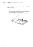
“1040 Memory/Wireless module/CPU (central processing unit) compartment
cover
” on page 38
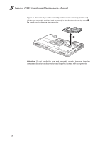
Figure 7. Removal steps of fan assembly and heat sink assembly
Note:
Remove three screws
1
, one screw
2
and four spring screws
3
.
Unplug the connector in the direction shown by arrow
4
.
4
3
3
3
3
1
1
1
2
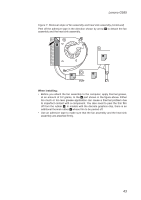
When installing:
Make sure that the fan connector is attached firmly to the
system board.
Step
Screw (quantity)
Color
Torque
1
M2.0 × 4 mm, flat-head, nylon-coated (3)
Black
1.5~2.0 kgf·cm
2
M2.0 × 3 mm, flat-head, nylon-coated (1)
Black
1.0~1.5 kgf·cm
3
M2.0 × 3.2 mm, with spring, nylon-coated (4)
Silver
2.0~2.5 kgf·cm