Lenovo G555 Lenovo G555 Hardware Maintenance Manual V2.0 - Page 73
Removal steps of LCD panel and hinges continued, Remove eight screws
 |
View all Lenovo G555 manuals
Add to My Manuals
Save this manual to your list of manuals |
Page 73 highlights
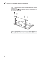
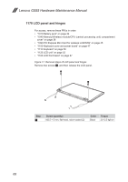
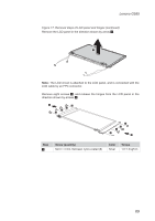
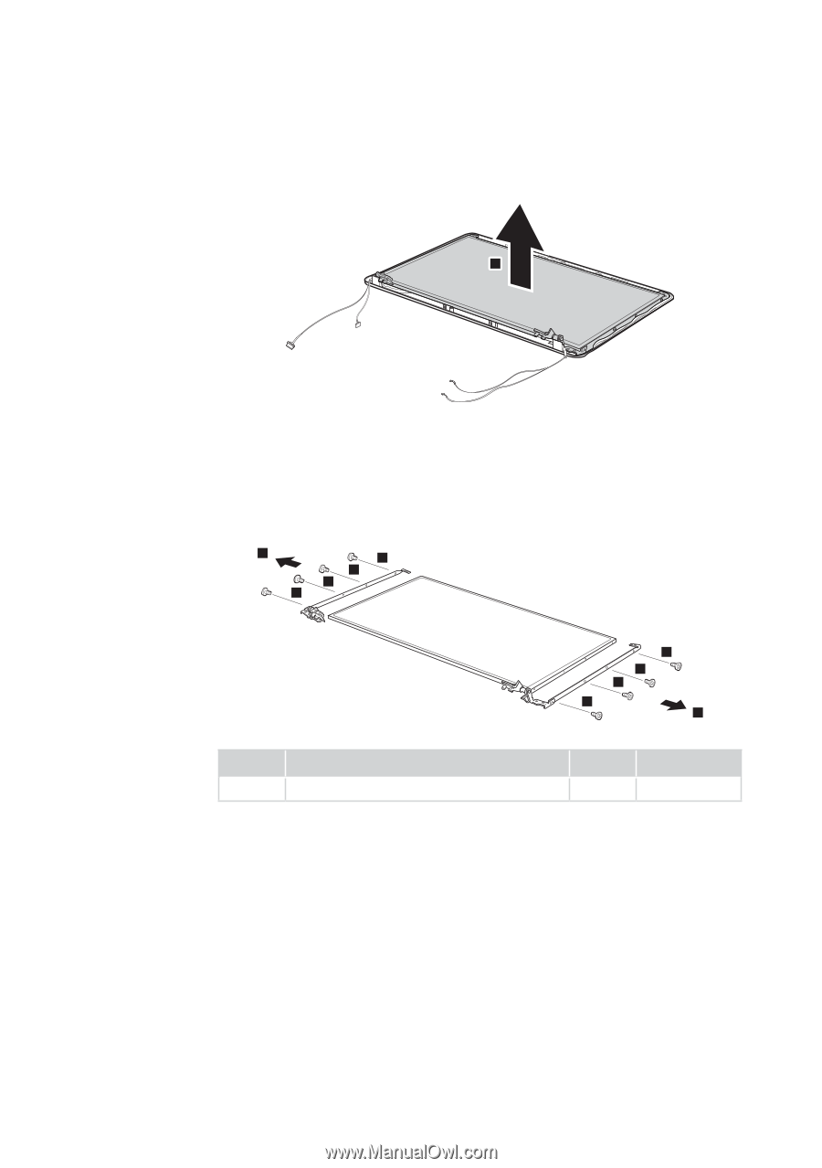
Lenovo G555 Figure 17. Removal steps of LCD panel and hinges (continued) Remove the LCD panel in the direction shown by arrow 2. 2 Note: The LCD circuit is attached to the LCD panel, and is connected with the LCD cable by an FPC connector. Remove eight screws 3, and release the hinges from the LCD panel in the direction shown by arrows 4. 4 3 3 3 3 3 3 3 3 4 Step 3 Screw (quantity) M2.0 × 3 mm, flat-head, nylon-coated (8) Color Silver Torque 1.0~1.5 kgf·cm 69
-
 1
1 -
2
-
3
-
4
-
5
-
6
-
7
-
8
-
9
-
10
-
11
-
12
-
13
-
14
-
15
-
16
-
17
-
18
-
19
-
20
-
21
-
22
-
23
-
24
-
25
-
26
-
27
-
28
-
29
-
30
-
31
-
32
-
33
-
34
-
35
-
36
-
37
-
38
-
39
-
40
-
41
-
42
-
43
-
44
-
45
-
46
-
47
-
48
-
49
-
50
-
51
-
52
-
53
-
54
-
55
-
56
-
57
-
58
-
59
-
60
-
61
-
62
-
63
-
64
-
65
-
66
-
67
-
 68
68 -
 69
69 -
 70
70 -
 71
71 -
 72
72 -
 73
73 -
 74
74 -
 75
75 -
 76
76 -
 77
77 -
 78
78 -
79
-
80
-
81
-
82
-
83
-
84
-
85
-
86
-
87
-
88
-
89
-
90
-
91
-
92
 |
 |
69
Lenovo G555
Figure 17. Removal steps of LCD panel and hinges (continued)
Remove the LCD panel in the direction shown by arrow
2
.
2
Note:
The LCD circuit is attached to the LCD panel, and is connected with the
LCD cable by an FPC connector.
Remove eight screws
3
, and release the hinges from the LCD panel in the
direction shown by arrows
4
.
3
3
3
3
4
3
3
3
3
4
Step
Screw (quantity)
Color
Torque
3
M2.0 × 3 mm, flat-head, nylon-coated (8)
Silver
1.0~1.5 kgf·cm