Lenovo G555 Lenovo G555 Hardware Maintenance Manual V2.0 - Page 65
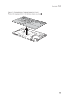
Removal steps of system board continued
 |
View all Lenovo G555 manuals
Add to My Manuals
Save this manual to your list of manuals |
Page 65 highlights
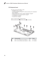
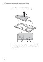
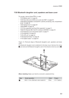
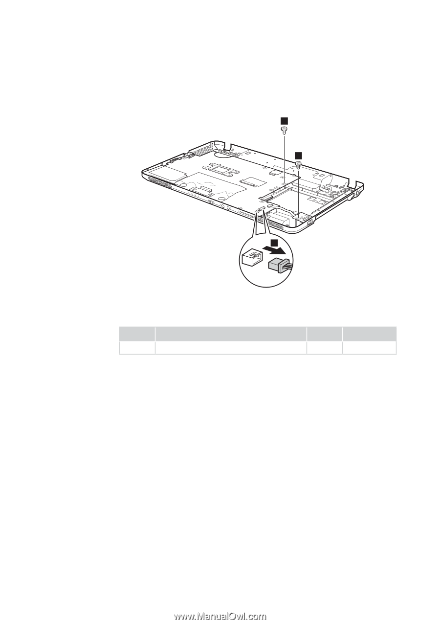
Lenovo G555 Figure 14. Removal steps of system board (continued) Unplug two connectors (bluetooth connector and speakers connector) in the direction shown by arrow 2, and remove two screws 3. 3 3 2 When installing: Make sure that the connectors are attached firmly. Step 3 Screw (quantity) M2.5 × 6 mm, flat-head, nylon-coated (2) Color Black Torque 2.0~2.5 kgf·cm 61
-
 1
1 -
2
-
3
-
4
-
5
-
6
-
7
-
8
-
9
-
10
-
11
-
12
-
13
-
14
-
15
-
16
-
17
-
18
-
19
-
20
-
21
-
22
-
23
-
24
-
25
-
26
-
27
-
28
-
29
-
30
-
31
-
32
-
33
-
34
-
35
-
36
-
37
-
38
-
39
-
40
-
41
-
42
-
43
-
44
-
45
-
46
-
47
-
48
-
49
-
50
-
51
-
52
-
53
-
54
-
55
-
56
-
57
-
58
-
59
-
 60
60 -
 61
61 -
 62
62 -
 63
63 -
 64
64 -
 65
65 -
 66
66 -
 67
67 -
 68
68 -
 69
69 -
 70
70 -
71
-
72
-
73
-
74
-
75
-
76
-
77
-
78
-
79
-
80
-
81
-
82
-
83
-
84
-
85
-
86
-
87
-
88
-
89
-
90
-
91
-
92
 |
 |
61
Lenovo G555
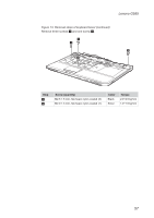
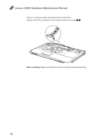
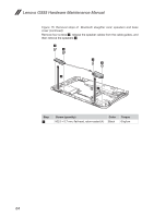
Figure 14. Removal steps of system board (continued)
Unplug two connectors (bluetooth connector and speakers connector) in the
direction shown by arrow
2
, and remove two screws
3
.
3
3
2
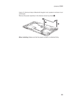
When installing:
Make sure that the connectors are attached firmly.
Step
Screw (quantity)
Color
Torque
3
M2.5 × 6 mm, flat-head, nylon-coated (2)
Black
2.0~2.5 kgf·cm