Lenovo G555 Lenovo G555 Hardware Maintenance Manual V2.0 - Page 48
CPU, Removal steps of CPU
 |
View all Lenovo G555 manuals
Add to My Manuals
Save this manual to your list of manuals |
Page 48 highlights
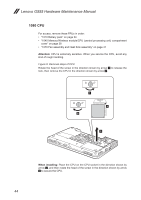
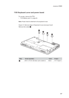
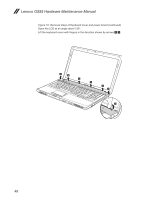
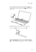
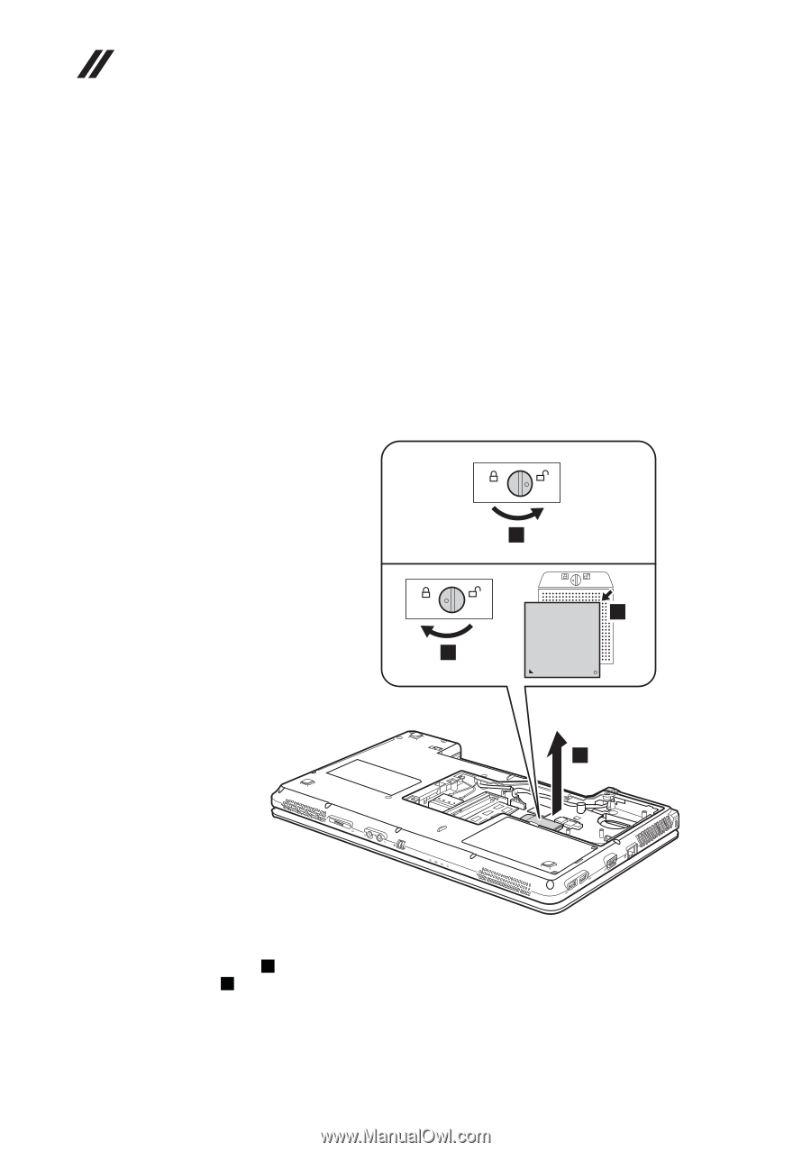
Lenovo G555 Hardware Maintenance Manual 1080 CPU For access, remove these FRUs in order: •• "1010 Battery pack" on page 34 •• "1040 Memory/Wireless module/CPU (central processing unit) compartment cover" on page 38 •• "1070 Fan assembly and Heat Sink assembly" on page 41 Attention: CPU is extremely sensitive. When you service the CPU, avoid any kind of rough handling. Figure 8. Removal steps of CPU Rotate the head of the screw in the direction shown by arrow 1 to release the lock, then remove the CPU in the direction shown by arrow 2. 1 a b 2 When installing: Place the CPU on the CPU socket in the direction shown by arrow a , and then rotate the head of the screw in the direction shown by arrow b to secure the CPU. 44
-
 1
1 -
2
-
3
-
4
-
5
-
6
-
7
-
8
-
9
-
10
-
11
-
12
-
13
-
14
-
15
-
16
-
17
-
18
-
19
-
20
-
21
-
22
-
23
-
24
-
25
-
26
-
27
-
28
-
29
-
30
-
31
-
32
-
33
-
34
-
35
-
36
-
37
-
38
-
39
-
40
-
41
-
42
-
 43
43 -
 44
44 -
 45
45 -
 46
46 -
 47
47 -
 48
48 -
 49
49 -
 50
50 -
 51
51 -
 52
52 -
 53
53 -
54
-
55
-
56
-
57
-
58
-
59
-
60
-
61
-
62
-
63
-
64
-
65
-
66
-
67
-
68
-
69
-
70
-
71
-
72
-
73
-
74
-
75
-
76
-
77
-
78
-
79
-
80
-
81
-
82
-
83
-
84
-
85
-
86
-
87
-
88
-
89
-
90
-
91
-
92
 |
 |
44
Lenovo G555 Hardware Maintenance Manual
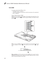
1080 CPU
For access, remove these FRUs in order:
•
“1010 Battery pack” on page 34
•
“1040 Memory/Wireless module/CPU (central processing unit) compartment
cover
” on page 38
•
“1070 Fan assembly and Heat Sink assembly” on page 41
Attention:
CPU is extremely sensitive. When you service the CPU, avoid any
kind of rough handling.
Figure 8. Removal steps of CPU
Rotate the head of the screw in the direction shown by arrow
1
to release the
lock, then remove the CPU in the direction shown by arrow
2
.
2
a
b
1
When installing:
Place the CPU on the CPU socket in the direction shown by
arrow
a
, and then rotate the head of the screw in the direction shown by arrow
b
to secure the CPU.