Lenovo G555 Lenovo G555 Hardware Maintenance Manual V2.0 - Page 74
Integrated camera - keyboard replacement
 |
View all Lenovo G555 manuals
Add to My Manuals
Save this manual to your list of manuals |
Page 74 highlights
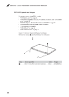
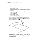
Lenovo G555 Hardware Maintenance Manual 1180 Integrated camera For access, remove these FRUs in order: •• "1010 Battery pack" on page 34 •• "1040 Memory/Wireless module/CPU (central processing unit) compartment cover" on page 38 •• "1090 PCI Express Mini Card for wireless LAN/WAN" on page 45 •• "1100 Keyboard cover and power board" on page 47 •• "1110 Keyboard" on page 50 •• "1120 LCD unit" on page 52 •• "1160 LCD front bezel" on page 67 •• "1170 LCD panel and hinges" on page 68 Figure 18. Removal steps of integrated camera Note: The integrated camera is attached to the top center of the LCD cover. Detach the connector in the direction shown by arrow 1 and then remove the integrated camera from the LCD cover 2. 1 2 When installing: Attach the integrated camera to the top center of the LCD cover and ajust the placement of it to make sure the connector is attached firmly. When replacing the integrated camera, route the connector cable as shown in the figure above. 70
-
 1
1 -
2
-
3
-
4
-
5
-
6
-
7
-
8
-
9
-
10
-
11
-
12
-
13
-
14
-
15
-
16
-
17
-
18
-
19
-
20
-
21
-
22
-
23
-
24
-
25
-
26
-
27
-
28
-
29
-
30
-
31
-
32
-
33
-
34
-
35
-
36
-
37
-
38
-
39
-
40
-
41
-
42
-
43
-
44
-
45
-
46
-
47
-
48
-
49
-
50
-
51
-
52
-
53
-
54
-
55
-
56
-
57
-
58
-
59
-
60
-
61
-
62
-
63
-
64
-
65
-
66
-
67
-
68
-
 69
69 -
 70
70 -
 71
71 -
 72
72 -
 73
73 -
 74
74 -
 75
75 -
 76
76 -
 77
77 -
 78
78 -
 79
79 -
80
-
81
-
82
-
83
-
84
-
85
-
86
-
87
-
88
-
89
-
90
-
91
-
92
 |
 |
