Lenovo Horizon 2 27 Table PC Lenovo Horizon 2 27 All-In-One PC Hardware Mainte - Page 38
Replacingthepowerswitchboard
 |
View all Lenovo Horizon 2 27 Table PC manuals
Add to My Manuals
Save this manual to your list of manuals |
Page 38 highlights
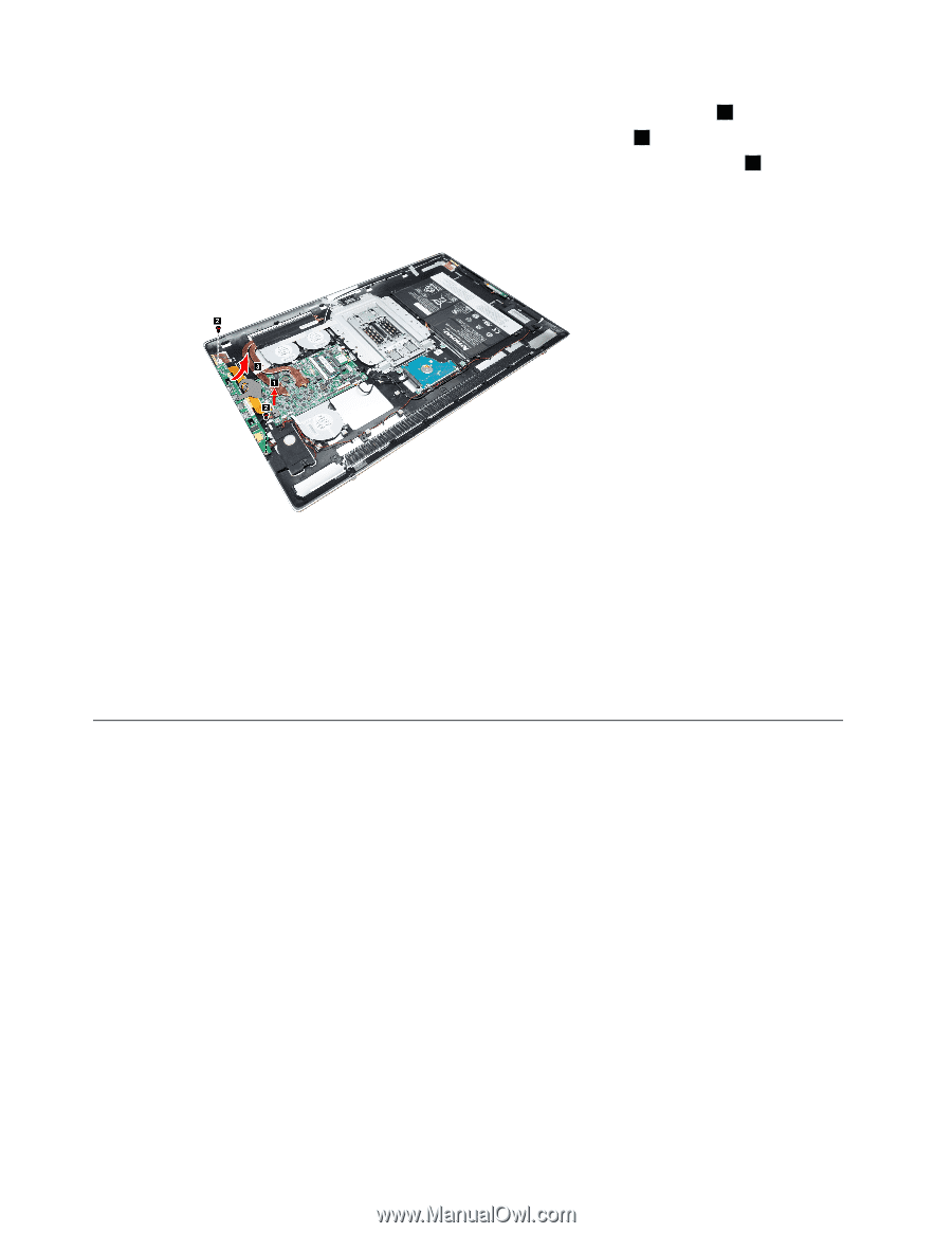
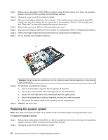
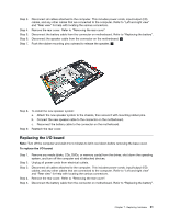
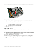
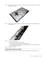
Step 6. Step 7. Step 8. Disconnect the power connector cable from the connector on the motherboard. 1 Remove the two screws that secure the I/O board to the rear cover. 2 Slide out the I/O board as shown and disconnect the data cable from the I/O board. 3 Step 9. To install the new I/O board: a. Connect the data cable to connector on the new I/O board. b. Line up the holes on the new I/O board with the mounting holes on the I/O board and secure the I/O board to the rear cover with the two screws. c. Connect the power connector cable to the connector on the motherboard. d. Reconnect the battery cable to the connector on the motherboard. Step 10. Reattach the rear cover. Replacing the power switch board Note: Turn off the computer and wait 3 to 5 minutes to let it cool down before removing the base cover. To replace the power switch board: Step 1. Step 2. Step 3. Step 4. Step 5. Step 6. Remove any media (disks, CDs, DVDs, or memory cards) from the drives, shut down the operating system, and turn off the computer and all attached devices. Unplug all power cords from electrical outlets. Disconnect all cables attached to the computer. This includes power cords, input/output (I/O) cables, and any other cables that are connected to the computer. Refer to "Left and right view" and "Rear view" for help with locating the various connectors. Remove the rear cover. Refer to "Removing the rear cover". Disconnect the battery cable from the connector on motherboard. Refer to "Replacing the battery". Disconnect the power cable from the power switch board. 32 IdeaCentre Horizon 2 27 All-In-One PC Hardware Maintenance Manual
-
 1
1 -
2
-
3
-
4
-
5
-
6
-
7
-
8
-
9
-
10
-
11
-
12
-
13
-
14
-
15
-
16
-
17
-
18
-
19
-
20
-
21
-
22
-
23
-
24
-
25
-
26
-
27
-
28
-
29
-
30
-
31
-
32
-
 33
33 -
 34
34 -
 35
35 -
 36
36 -
 37
37 -
 38
38 -
 39
39 -
 40
40 -
 41
41 -
 42
42 -
 43
43 -
44
-
45
-
46
-
47
-
48
-
49
 |
 |