Lenovo NetVista Hardware Maintenance Manual (HMM) for NetVista 2292, 6343, 634 - Page 37
SeeLocating
 |
View all Lenovo NetVista manuals
Add to My Manuals
Save this manual to your list of manuals |
Page 37 highlights
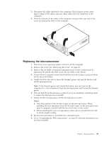
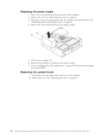
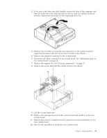
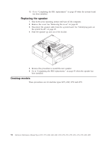
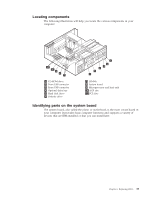
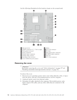
3. Pivot one of the drive bay latch handles toward the front of the computer and then pivot the drive bay cage upward, as shown, until it is latched in the up position. Repeat this procedure for the remaining drive bay. 4. Remove the air baffle covering the microprocessor on the system board by squeezing the plastic tabs that secure the air baffle to the chassis. 5. Remove any adapters connected to the system board. 6. Disconnect all cables connected to the system board. See "Identifying parts on the system board" on page 28. 7. Remove the support bar. See"Locating components" on page 27. 8. Remove the screws that hold the system board to the chassis. 9. Lift the system board out. 10. Remove the microprocessor from the system board and install it on the new system board. 11. Remove the memory modules from the system board and install them on the new system board. 12. Reverse this procedure to install the new system board. Chapter 6. Replacing FRUs 31
-
 1
1 -
2
-
3
-
4
-
5
-
6
-
7
-
8
-
9
-
10
-
11
-
12
-
13
-
14
-
15
-
16
-
17
-
18
-
19
-
20
-
21
-
22
-
23
-
24
-
25
-
26
-
27
-
28
-
29
-
30
-
31
-
 32
32 -
 33
33 -
 34
34 -
 35
35 -
 36
36 -
 37
37 -
 38
38 -
 39
39 -
 40
40 -
 41
41 -
 42
42 -
43
-
44
-
45
-
46
-
47
-
48
-
49
-
50
-
51
-
52
-
53
-
54
-
55
-
56
-
57
-
58
-
59
-
60
-
61
-
62
-
63
-
64
-
65
-
66
-
67
-
68
-
69
-
70
-
71
-
72
-
73
-
74
-
75
-
76
-
77
-
78
-
79
-
80
-
81
-
82
-
83
-
84
-
85
-
86
-
87
-
88
-
89
-
90
-
91
-
92
-
93
-
94
-
95
-
96
-
97
-
98
-
99
-
100
-
101
-
102
-
103
-
104
-
105
-
106
-
107
-
108
-
109
-
110
-
111
-
112
-
113
-
114
-
115
-
116
-
117
-
118
-
119
-
120
-
121
-
122
-
123
-
124
-
125
-
126
-
127
-
128
-
129
-
130
-
131
-
132
-
133
-
134
-
135
-
136
-
137
-
138
-
139
-
140
-
141
-
142
-
143
-
144
-
145
-
146
-
147
-
148
-
149
-
150
-
151
-
152
-
153
-
154
-
155
-
156
-
157
-
158
-
159
-
160
-
161
-
162
-
163
-
164
-
165
-
166
-
167
-
168
-
169
-
170
-
171
-
172
-
173
-
174
-
175
-
176
-
177
-
178
-
179
-
180
-
181
-
182
-
183
-
184
-
185
-
186
-
187
-
188
-
189
-
190
-
191
-
192
-
193
-
194
-
195
-
196
-
197
-
198
-
199
-
200
-
201
-
202
-
203
-
204
-
205
-
206
-
207
-
208
-
209
-
210
-
211
-
212
-
213
-
214
-
215
-
216
-
217
-
218
-
219
-
220
-
221
-
222
-
223
-
224
-
225
-
226
-
227
-
228
-
229
-
230
 |
 |
