Lenovo NetVista Hardware Maintenance Manual (HMM) for NetVista 2292, 6343, 634 - Page 42
Replacing, system, board
 |
View all Lenovo NetVista manuals
Add to My Manuals
Save this manual to your list of manuals |
Page 42 highlights
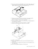
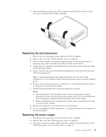
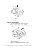
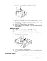
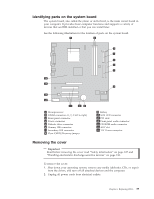
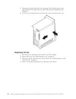
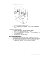
4. Remove the screws that hold the power supply in place. 5. Lift the power supply out. 6. Reverse this procedure to install the new power supply. 7. Go to "Completing the FRU replacement." on page 45 when the power supply has been installed. Replacing the system board 1. Shut down your operating system and turn off the computer. 2. Remove the cover. See "Removing the cover" on page 34. 3. Pivot the drive bay latch handle toward the front of the computer and then pivot the drive bay cage upward, as shown, until it is latched in the up right position. 4. Remove any adapters connected to the system board. 5. Disconnect all cables connected to the system board. See "Identifying parts on the system board" on page 33. 6. Remove the support bar. See"Locating components" on page 33. 36 Hardware Maintenance Manual Types 2292, 2273, 6043, 6343, 6349, 6350, 6790, 6791, 6792, 6793, 6794, 6795, 6823, 6825
-
 1
1 -
2
-
3
-
4
-
5
-
6
-
7
-
8
-
9
-
10
-
11
-
12
-
13
-
14
-
15
-
16
-
17
-
18
-
19
-
20
-
21
-
22
-
23
-
24
-
25
-
26
-
27
-
28
-
29
-
30
-
31
-
32
-
33
-
34
-
35
-
36
-
 37
37 -
 38
38 -
 39
39 -
 40
40 -
 41
41 -
 42
42 -
 43
43 -
 44
44 -
 45
45 -
 46
46 -
 47
47 -
48
-
49
-
50
-
51
-
52
-
53
-
54
-
55
-
56
-
57
-
58
-
59
-
60
-
61
-
62
-
63
-
64
-
65
-
66
-
67
-
68
-
69
-
70
-
71
-
72
-
73
-
74
-
75
-
76
-
77
-
78
-
79
-
80
-
81
-
82
-
83
-
84
-
85
-
86
-
87
-
88
-
89
-
90
-
91
-
92
-
93
-
94
-
95
-
96
-
97
-
98
-
99
-
100
-
101
-
102
-
103
-
104
-
105
-
106
-
107
-
108
-
109
-
110
-
111
-
112
-
113
-
114
-
115
-
116
-
117
-
118
-
119
-
120
-
121
-
122
-
123
-
124
-
125
-
126
-
127
-
128
-
129
-
130
-
131
-
132
-
133
-
134
-
135
-
136
-
137
-
138
-
139
-
140
-
141
-
142
-
143
-
144
-
145
-
146
-
147
-
148
-
149
-
150
-
151
-
152
-
153
-
154
-
155
-
156
-
157
-
158
-
159
-
160
-
161
-
162
-
163
-
164
-
165
-
166
-
167
-
168
-
169
-
170
-
171
-
172
-
173
-
174
-
175
-
176
-
177
-
178
-
179
-
180
-
181
-
182
-
183
-
184
-
185
-
186
-
187
-
188
-
189
-
190
-
191
-
192
-
193
-
194
-
195
-
196
-
197
-
198
-
199
-
200
-
201
-
202
-
203
-
204
-
205
-
206
-
207
-
208
-
209
-
210
-
211
-
212
-
213
-
214
-
215
-
216
-
217
-
218
-
219
-
220
-
221
-
222
-
223
-
224
-
225
-
226
-
227
-
228
-
229
-
230
 |
 |
