Lenovo Q200 Q200 Hardware Replacement Guide
Lenovo Q200 Manual
 |
View all Lenovo Q200 manuals
Add to My Manuals
Save this manual to your list of manuals |
Lenovo Q200 manual content summary:
- Lenovo Q200 | Q200 Hardware Replacement Guide - Page 1
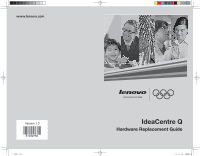
www.lenovo.com Version 1.0 31032756 31032756_HRG_FM_EN.indd 1 WORLDWIDE PARTNER IdeaCentre Q Hardware Replacement Guide 2007.12.21 4:57:27 PM - Lenovo Q200 | Q200 Hardware Replacement Guide - Page 2
Hardware Replacement Guide 31032756_HaWaii-HRG_EN.indd 39 2008.1.8 3:31:49 PM - Lenovo Q200 | Q200 Hardware Replacement Guide - Page 3
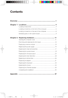
Contents Overview 1 Chapter 1 Locations 4 Locating components 4 Locating connectors on the front of the computer 5 Locating connectors on the rear of the computer 6 Identifying parts on the system board 9 Chapter 2 Replacing hardware 11 Opening the computer cover 11 Removing and replacing - Lenovo Q200 | Q200 Hardware Replacement Guide - Page 4
by trained service personnel without the need for step-by-step procedures. Note Use only parts provided by Lenovo™. The description of the TV card in this manual is only used for the machines which have the TV card. It is invalid for those machines which do not have TV card. This guide contains - Lenovo Q200 | Q200 Hardware Replacement Guide - Page 5
Publications • Troubleshooting information • Parts information • Links to other useful sources of information To access this information, go to http://www.lenovo.com/support. Tools static electricity in the package 2 Hardware Replacement Guide 31032756_HaWaii-HRG_EN.indd 2 2008.1.8 3:31:22 PM - Lenovo Q200 | Q200 Hardware Replacement Guide - Page 6
surface and place the part on it. • Do not place the part on the computer cover or other metal surface. 31032756_HaWaii-HRG_EN.indd 3 Hardware Replacement Guide 3 2008.1.8 3:31:22 PM - Lenovo Q200 | Q200 Hardware Replacement Guide - Page 7
computer cover, refer to "Removing the computer cover". Locating components The following illustration will help you locate the various components in your computer. 4 Hardware Replacement Guide 31032756_HaWaii-HRG_EN.indd 4 2008.1.8 4:12:29 PM - Lenovo Q200 | Q200 Hardware Replacement Guide - Page 8
. D-5 xD CF I/II/MD D-1 D-2 D-4 D-3 MS/Duo/ProDuo SD/Mini/HC/MiniHC MMC/RS/Plus/Mobile D-1 F-1 Power switch on the top 31032756_HaWaii-HRG_EN.indd 5 Hardware Replacement Guide 5 2008.1.8 3:31:24 PM - Lenovo Q200 | Q200 Hardware Replacement Guide - Page 9
be similar to, but possibly not identical to these. Following the illustrations is a key that explains the symbol callouts used in the figures. 6 Hardware Replacement Guide 31032756_HaWaii-HRG_EN.indd 6 2008.1.8 3:31:25 PM - Lenovo Q200 | Q200 Hardware Replacement Guide - Page 10
may have some of these connectors, but not have all of them. Use the correct connector according to the usage. 31032756_HaWaii-HRG_EN.indd 7 Hardware Replacement Guide 7 2008.1.8 3:31:26 PM - Lenovo Q200 | Q200 Hardware Replacement Guide - Page 11
models are equipped with this connector) S --- S Video Connector: To connect the data cable of the S video. (Some models are equipped with this connector.) 8 Hardware Replacement Guide 31032756_HaWaii-HRG_EN.indd 8 2008.1.8 3:31:28 PM - Lenovo Q200 | Q200 Hardware Replacement Guide - Page 12
The system board (sometimes called the planar or motherboard) is the main circuit board in your computer. It provides basic computer functions and supports a variety of devices that are factory-installed or that you can install later. The following illustration shows the locations of parts on the - Lenovo Q200 | Q200 Hardware Replacement Guide - Page 13
connector PCI Express x1 adapter connector PCI adapter connectors (2) Battery PCI Express x16 graphics adapter connector System fan connector 12v power connector 10 Hardware Replacement Guide 31032756_HaWaii-HRG_EN.indd 10 2008.1.8 3:31:30 PM - Lenovo Q200 | Q200 Hardware Replacement Guide - Page 14
included with your computer or in the Hardware Maintenance Manual (HMM) for the computer. To obtain copies of the Safety and Warranty Guide or HMM, go to the Support Web site at http://www.lenovo.com/support. Note Use only parts provided by Lenovo. Opening the computer cover Important Turn off the - Lenovo Q200 | Q200 Hardware Replacement Guide - Page 15
on the bottom of the bezel with the corresponding holes in the chassis, then snap it into position at the bottom and 12 Hardware Replacement Guide 31032756_HaWaii-HRG_EN.indd 12 2008.1.8 3:31:31 PM - Lenovo Q200 | Q200 Hardware Replacement Guide - Page 16
that was included with your computer or in the Hardware Maintenance Manual (HMM) for the computer. To obtain copies of the Safety and Warranty Guide or HMM, go to the Support Web site at http://www.lenovo.com/support. To replace a memory module: 1. Open the computer cover. Refer to "Opening the - Lenovo Q200 | Q200 Hardware Replacement Guide - Page 17
that was included with your computer or in the Hardware Maintenance Manual (HMM) for the computer. To obtain copies of the Safety and Warranty Guide or HMM, go to the Support Web site at http://www.lenovo.com/support. To replace the power supply: 1. Remove the three screws at the rear of the chassis - Lenovo Q200 | Q200 Hardware Replacement Guide - Page 18
2. Open the computer cover. Refer to "Opening the computer cover". Note: For this procedure, it helps to lay the computer on its side. 3. Pivot the drive bay assembly upward to gain access to the system board. 31032756_HaWaii-HRG_EN.indd 15 Hardware Replacement Guide 15 2008.1.8 3:31:33 PM - Lenovo Q200 | Q200 Hardware Replacement Guide - Page 19
the power supply cables from the cable clips and ties. 6. Slide the power supply assembly forward and remove it from the computer. 16 Hardware Replacement Guide 31032756_HaWaii-HRG_EN.indd 16 2008.1.8 3:31:34 PM - Lenovo Q200 | Q200 Hardware Replacement Guide - Page 20
was included with your computer or in the Hardware Maintenance Manual (HMM) for the computer. To obtain copies of the Safety and Warranty Guide or HMM, go to the Support Web site at http://www.lenovo.com/support. To replace the heat sink assembly: 1. Remove the computer cover. Refer to "Removing - Lenovo Q200 | Q200 Hardware Replacement Guide - Page 21
with those in the chassis.Insert and tighten the screws that secure the system board. Refer to the "Replacing the system board". 18 Hardware Replacement Guide 31032756_HaWaii-HRG_EN.indd 18 2008.1.8 3:31:35 PM - Lenovo Q200 | Q200 Hardware Replacement Guide - Page 22
the system board. Refer to the "Identifying parts on the system board". 7. Remove the screws that secure the system board to the chassis. Hardware Replacement Guide 19 31032756_HaWaii-HRG_EN.indd 19 2008.1.8 3:31:35 PM - Lenovo Q200 | Q200 Hardware Replacement Guide - Page 23
"Identifying parts on the system board". 12. Remove the four screws securing the heat sink and fan assembly to the system board. 20 Hardware Replacement Guide 31032756_HaWaii-HRG_EN.indd 20 2008.1.8 3:31:35 PM - Lenovo Q200 | Q200 Hardware Replacement Guide - Page 24
with anything. 14. To remove the microprocessor from the system board, lift the small handle and open the retainer . 31032756_HaWaii-HRG_EN.indd 21 Hardware Replacement Guide 21 2008.1.8 3:31:36 PM - Lenovo Q200 | Q200 Hardware Replacement Guide - Page 25
with your fingers, position the microprocessor so that the notches on the microprocessor are aligned with the tabs in the microprocessor socket. 22 Hardware Replacement Guide 31032756_HaWaii-HRG_EN.indd 22 2008.1.8 3:31:37 PM - Lenovo Q200 | Q200 Hardware Replacement Guide - Page 26
that was included with your computer or in the Hardware Maintenance Manual (HMM) for the computer. To obtain copies of the Safety and Warranty Guide or HMM, go to the Support Web site at http://www.lenovo.com/support. 31032756_HaWaii-HRG_EN.indd 23 Hardware Replacement Guide 23 2008.1.8 3:31:37 PM - Lenovo Q200 | Q200 Hardware Replacement Guide - Page 27
to "Identifying parts on the system board". 6. Remove the four screws securing the heat sink and fan assembly to the system board. 24 Hardware Replacement Guide 31032756_HaWaii-HRG_EN.indd 24 2008.1.8 3:31:37 PM - Lenovo Q200 | Q200 Hardware Replacement Guide - Page 28
and become contaminated. 8. To remove the microprocessor from the system board, lift the small handle and open the retainer . 31032756_HaWaii-HRG_EN.indd 25 Hardware Replacement Guide 25 2008.1.8 3:31:38 PM - Lenovo Q200 | Q200 Hardware Replacement Guide - Page 29
fully open. 11. Holding the microprocessor with your fingers, remove the protective cover that protects the gold contacts on the new microprocessor . 26 Hardware Replacement Guide 31032756_HaWaii-HRG_EN.indd 26 2008.1.8 3:31:38 PM - Lenovo Q200 | Q200 Hardware Replacement Guide - Page 30
on the top of the microprocessor. Each drop of grease should be 0.03ml (3 tick marks on the grease syringe). 31032756_HaWaii-HRG_EN.indd 27 Hardware Replacement Guide 27 2008.1.8 3:31:39 PM - Lenovo Q200 | Q200 Hardware Replacement Guide - Page 31
that was included with your computer or in the Hardware Maintenance Manual (HMM) for the computer. To obtain copies of the Safety and Warranty Guide or HMM, go to the Support Web site at http://www.lenovo.com/support. Important When you receive a new hard disk drive, you will also receive a set - Lenovo Q200 | Q200 Hardware Replacement Guide - Page 32
3. Disconnect the signal and power cables from the hard disk drive. 4. press the release button to pull the drive and bracket out of the drive bay by pulling on the blue handle. Hardware Replacement Guide 29 31032756_HaWaii-HRG_EN.indd 29 2008.1.8 3:31:40 PM - Lenovo Q200 | Q200 Hardware Replacement Guide - Page 33
that was included with your computer or in the Hardware Maintenance Manual (HMM) for the computer. To obtain copies of the Safety and Warranty Guide or HMM, go to the Support Web site at http://www.lenovo.com/support. To replace an optical drive 1. Open the computer cover. Refer to "Opening the - Lenovo Q200 | Q200 Hardware Replacement Guide - Page 34
that was included with your computer or in the Hardware Maintenance Manual (HMM) for the computer. To obtain copies of the Safety and Warranty Guide or HMM, go to the Support Web site at http://www.lenovo.com/support. To replace an adapter: 1. Open the computer cover. Refer to "Opening the computer - Lenovo Q200 | Q200 Hardware Replacement Guide - Page 35
3. Pulling the adapter out of the adapter connector by opening the retaining clips as shown. 4. Install the new adapter into the same adapter connector. 32 Hardware Replacement Guide 31032756_HaWaii-HRG_EN.indd 32 2008.1.8 3:31:41 PM - Lenovo Q200 | Q200 Hardware Replacement Guide - Page 36
that was included with your computer or in the Hardware Maintenance Manual (HMM) for the computer. To obtain copies of the Safety and Warranty Guide or HMM, go to the Support Web site at http://www.lenovo.com/support. To replace the keyboard: 1. Remove any media (diskettes, CDs, or tapes) from the - Lenovo Q200 | Q200 Hardware Replacement Guide - Page 37
that was included with your computer or in the Hardware Maintenance Manual (HMM) for the computer. To obtain copies of the Safety and Warranty Guide or HMM, go to the Support Web site at http://www.lenovo.com/support. To replace the mouse: 1. Remove any media (diskettes, CDs, or tapes) from the - Lenovo Q200 | Q200 Hardware Replacement Guide - Page 38
need to confirm the updated information in the Setup Utility program. Refer to "Starting the Setup Utility" in the User Guide or in the Hardware Maintenance Manual. To complete the part installation: 1. Ensure that all components have been reassembled correctly and that no tools or loose screws are - Lenovo Q200 | Q200 Hardware Replacement Guide - Page 39
rear of the computer". 5. To update your configuration settings, refer to "Starting the Setup Utility" in the User Guide or in the Hardware Maintenance Manual. Note: In most areas of the world, Lenovo requires the return of the defective CRU. Information about this will come with the CRU or will come - Lenovo Q200 | Q200 Hardware Replacement Guide - Page 40
for any inconsistency between the product and all the manuals included with your computer. For the latest information or any questions or comments, contact or visit Lenovo website: Service website: http://www.lenovo.com Hardware Replacement Guide 37 31032756_HaWaii-HRG_EN.indd 37 2008.1.8 3:31:44 - Lenovo Q200 | Q200 Hardware Replacement Guide - Page 41
included with your computer may not be reproduced or copied by any means without prior written permission of Lenovo (Beijing) Co., Ltd. Names or marks of certain companies mentioned in all the manuals included with your computer or this document are only used to state trademark rights, and they will
-
 1
1 -
 2
2 -
 3
3 -
 4
4 -
 5
5 -
 6
6 -
 7
7 -
8
-
9
-
10
-
11
-
12
-
13
-
14
-
15
-
16
-
17
-
18
-
19
-
20
-
21
-
22
-
23
-
24
-
25
-
26
-
27
-
28
-
29
-
30
-
31
-
32
-
33
-
34
-
35
-
36
-
37
-
38
-
39
-
40
-
41
 |
 |
www.lenovo.com
Version 1.0
WORLDWIDE PARTNER
IdeaCentre Q
Hardware Replacement Guide
31032756
3
032756
HRG
2007
22
4:57:27 P