Lenovo ThinkCentre M52 User Manual - Page 31
Installing, memory
 |
View all Lenovo ThinkCentre M52 manuals
Add to My Manuals
Save this manual to your list of manuals |
Page 31 highlights
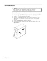
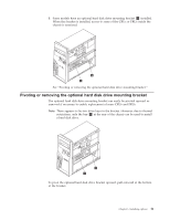
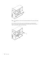
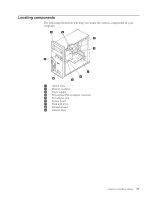
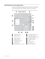
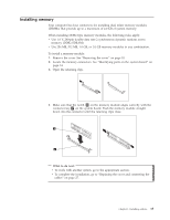
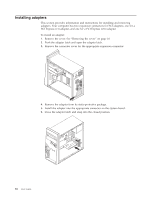
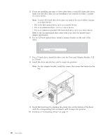
Installing memory Your computer has four connectors for installing dual inline memory modules (DIMMs) that provide up to a maximum of 4.0 GB of system memory. When installing DDR2 type memory modules, the following rules apply: v Use 1.8 V, 240-pin double data rate 2 synchronous dynamic random access memory (DDR2 SDRAM). v Use 256 MB, 512 MB, 1.0 GB, or 2.0 GB memory modules in any combination. To install a memory module: 1. Remove the cover. See "Removing the cover" on page 10. 2. Locate the memory connectors. See "Identifying parts on the system board" on page 14. 3. Open the retaining clips. 4. Make sure that the notch 1 on the memory module aligns correctly with the connector key 2 on the system board. Push the memory module straight down into the connector until the retaining clips close. What to do next: v To work with another option, go to the appropriate section. v To complete the installation, go to "Replacing the cover and connecting the cables" on page 27. Chapter 1. Installing options 15
-
 1
1 -
2
-
3
-
4
-
5
-
6
-
7
-
8
-
9
-
10
-
11
-
12
-
13
-
14
-
15
-
16
-
17
-
18
-
19
-
20
-
21
-
22
-
23
-
24
-
25
-
 26
26 -
 27
27 -
 28
28 -
 29
29 -
 30
30 -
 31
31 -
 32
32 -
 33
33 -
 34
34 -
 35
35 -
 36
36 -
37
-
38
-
39
-
40
-
41
-
42
-
43
-
44
-
45
-
46
-
47
-
48
-
49
-
50
-
51
-
52
-
53
-
54
-
55
-
56
-
57
-
58
-
59
-
60
-
61
-
62
-
63
-
64
-
65
-
66
-
67
-
68
 |
 |