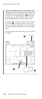
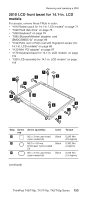
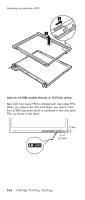
Lenovo ThinkPad T40 Hardware Maintenance Manual - Page 156
remove, plate, bracket, system, board, together., Attach, small, projections, cover, holes, provided
 |
View all Lenovo ThinkPad T40 manuals
Add to My Manuals
Save this manual to your list of manuals |
Page 156 highlights
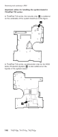
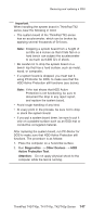
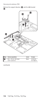
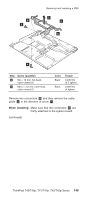
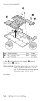
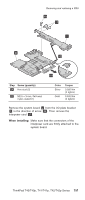
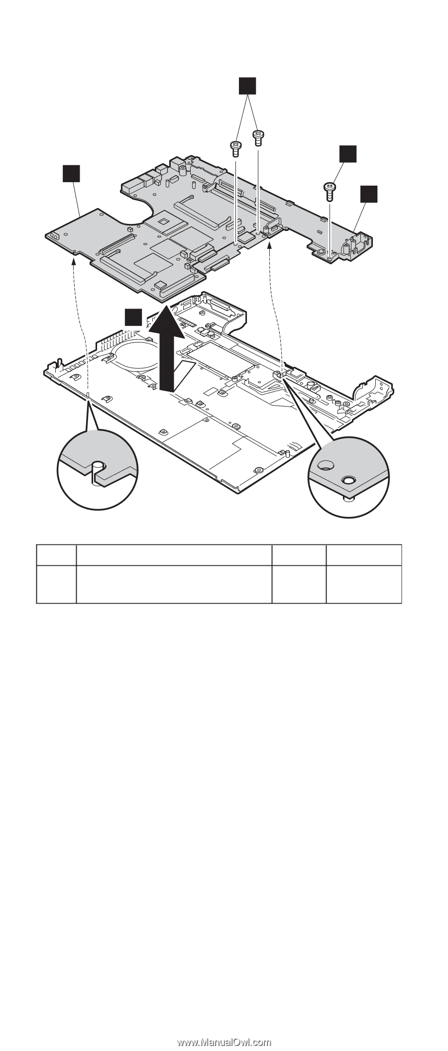
Removing and replacing a FRU 8 e 8 d 9 Step 8 Screw (quantity) M2 × 4 mm, bind-head, nylon-coated (3) Color Black Torque 0.245 Nm (2.5 kgfcm) In step 9 , remove the I/O plate bracket ( d ) and the system board ( e ) together. When installing: Attach the system board so that the two small projections on the base cover fit into the holes provided, and then secure the system board with the screw. (continued) 150 T40/T40p, T41/T41p, T42/T42p
-
 1
1 -
2
-
3
-
4
-
5
-
6
-
7
-
8
-
9
-
10
-
11
-
12
-
13
-
14
-
15
-
16
-
17
-
18
-
19
-
20
-
21
-
22
-
23
-
24
-
25
-
26
-
27
-
28
-
29
-
30
-
31
-
32
-
33
-
34
-
35
-
36
-
37
-
38
-
39
-
40
-
41
-
42
-
43
-
44
-
45
-
46
-
47
-
48
-
49
-
50
-
51
-
52
-
53
-
54
-
55
-
56
-
57
-
58
-
59
-
60
-
61
-
62
-
63
-
64
-
65
-
66
-
67
-
68
-
69
-
70
-
71
-
72
-
73
-
74
-
75
-
76
-
77
-
78
-
79
-
80
-
81
-
82
-
83
-
84
-
85
-
86
-
87
-
88
-
89
-
90
-
91
-
92
-
93
-
94
-
95
-
96
-
97
-
98
-
99
-
100
-
101
-
102
-
103
-
104
-
105
-
106
-
107
-
108
-
109
-
110
-
111
-
112
-
113
-
114
-
115
-
116
-
117
-
118
-
119
-
120
-
121
-
122
-
123
-
124
-
125
-
126
-
127
-
128
-
129
-
130
-
131
-
132
-
133
-
134
-
135
-
136
-
137
-
138
-
139
-
140
-
141
-
142
-
143
-
144
-
145
-
146
-
147
-
148
-
149
-
150
-
 151
151 -
 152
152 -
 153
153 -
 154
154 -
 155
155 -
 156
156 -
 157
157 -
 158
158 -
 159
159 -
 160
160 -
 161
161 -
162
-
163
-
164
-
165
-
166
-
167
-
168
-
169
-
170
-
171
-
172
-
173
-
174
-
175
-
176
-
177
-
178
-
179
-
180
-
181
-
182
-
183
-
184
-
185
-
186
-
187
-
188
-
189
-
190
-
191
-
192
-
193
-
194
-
195
-
196
-
197
-
198
-
199
-
200
-
201
-
202
-
203
-
204
-
205
-
206
-
207
-
208
-
209
-
210
-
211
-
212
-
213
-
214
-
215
-
216
-
217
-
218
-
219
-
220
-
221
-
222
-
223
-
224
-
225
-
226
-
227
-
228
-
229
-
230
-
231
-
232
-
233
-
234
-
235
-
236
-
237
-
238
-
239
-
240
-
241
-
242
-
243
-
244
-
245
-
246
-
247
-
248
-
249
-
250
-
251
-
252
-
253
-
254
-
255
-
256
-
257
-
258
-
259
-
260
 |
 |
8
d
e
9
8
Step
Screw
(quantity)
Color
Torque
±8²
M2
×
4
mm,
bind-head,
nylon-coated
(3)
Black
0.245
Nm
(2.5
kgfcm)
In
step
±9²
,
remove
the
I/O
plate
bracket
(
±d²
)
and
the
system
board
(
±e²
)
together.
When
installing:
Attach
the
system
board
so
that
the
two
small
projections
on
the
base
cover
fit
into
the
holes
provided,
and
then
secure
the
system
board
with
the
screw.
(continued)
Removing
and
replacing
a
FRU
150
T40/T40p,
T41/T41p,
T42/T42p