Lenovo ThinkPad T40 Hardware Maintenance Manual - Page 186
screwdriver
 |
View all Lenovo ThinkPad T40 manuals
Add to My Manuals
Save this manual to your list of manuals |
Page 186 highlights
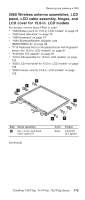
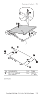
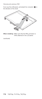
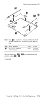
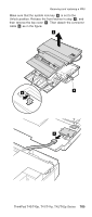
Removing and replacing a FRU Cable routing: When you reassemble the LCD unit, do as follows: At the left-top corner of the LCD unit, route the antenna cable as in a . Do not route the cable over the bracket. To do so, the cable might be pinched between the LCD front bezel and the LCD cover, and the cable or the other parts might be damaged or might not be installed properly. At the points shown as V, route the cable as it goes under the projections as in b . At the points shown as , push the cable into the ditch between the LCD cover and the bracket by using a screwdriver as in c . a b b c (continued) 180 T40/T40p, T41/T41p, T42/T42p
-
 1
1 -
2
-
3
-
4
-
5
-
6
-
7
-
8
-
9
-
10
-
11
-
12
-
13
-
14
-
15
-
16
-
17
-
18
-
19
-
20
-
21
-
22
-
23
-
24
-
25
-
26
-
27
-
28
-
29
-
30
-
31
-
32
-
33
-
34
-
35
-
36
-
37
-
38
-
39
-
40
-
41
-
42
-
43
-
44
-
45
-
46
-
47
-
48
-
49
-
50
-
51
-
52
-
53
-
54
-
55
-
56
-
57
-
58
-
59
-
60
-
61
-
62
-
63
-
64
-
65
-
66
-
67
-
68
-
69
-
70
-
71
-
72
-
73
-
74
-
75
-
76
-
77
-
78
-
79
-
80
-
81
-
82
-
83
-
84
-
85
-
86
-
87
-
88
-
89
-
90
-
91
-
92
-
93
-
94
-
95
-
96
-
97
-
98
-
99
-
100
-
101
-
102
-
103
-
104
-
105
-
106
-
107
-
108
-
109
-
110
-
111
-
112
-
113
-
114
-
115
-
116
-
117
-
118
-
119
-
120
-
121
-
122
-
123
-
124
-
125
-
126
-
127
-
128
-
129
-
130
-
131
-
132
-
133
-
134
-
135
-
136
-
137
-
138
-
139
-
140
-
141
-
142
-
143
-
144
-
145
-
146
-
147
-
148
-
149
-
150
-
151
-
152
-
153
-
154
-
155
-
156
-
157
-
158
-
159
-
160
-
161
-
162
-
163
-
164
-
165
-
166
-
167
-
168
-
169
-
170
-
171
-
172
-
173
-
174
-
175
-
176
-
177
-
178
-
179
-
180
-
 181
181 -
 182
182 -
 183
183 -
 184
184 -
 185
185 -
 186
186 -
 187
187 -
 188
188 -
 189
189 -
 190
190 -
 191
191 -
192
-
193
-
194
-
195
-
196
-
197
-
198
-
199
-
200
-
201
-
202
-
203
-
204
-
205
-
206
-
207
-
208
-
209
-
210
-
211
-
212
-
213
-
214
-
215
-
216
-
217
-
218
-
219
-
220
-
221
-
222
-
223
-
224
-
225
-
226
-
227
-
228
-
229
-
230
-
231
-
232
-
233
-
234
-
235
-
236
-
237
-
238
-
239
-
240
-
241
-
242
-
243
-
244
-
245
-
246
-
247
-
248
-
249
-
250
-
251
-
252
-
253
-
254
-
255
-
256
-
257
-
258
-
259
-
260
 |
 |

Cable
routing:
When
you
reassemble
the
LCD
unit,
do
as
follows:
At
the
left-top
corner
of
the
LCD
unit,
route
the
antenna
cable
as
in
±a²
.
Do
not
route
the
cable
over
the
bracket.
To
do
so,
the
cable
might
be
pinched
between
the
LCD
front
bezel
and
the
LCD
cover,
and
the
cable
or
the
other
parts
might
be
damaged
or
might
not
be
installed
properly.
At
the
points
shown
as
V
,
route
the
cable
as
it
goes
under
the
projections
as
in
±b²
.
At
the
points
shown
as
²
,
push
the
cable
into
the
ditch
between
the
LCD
cover
and
the
bracket
by
using
a
screwdriver
as
in
±c²
.
c
a
b
b
(continued)
Removing
and
replacing
a
FRU
180
T40/T40p,
T41/T41p,
T42/T42p